I am writing this blog article to discuss an issue I have run into with saw blade length. This issue is a moot point for the parallel link saws I have used, as they have a slot the blade goes in and the blade can be moved up and down in the slot. For the Hawk and the Shopsmith, the blade is fully inserted to the bottoms of the blade holders. It appears that the Hegner saws would be impacted as well.
First, a little background to understand why blade length is important. I have used a few different saws through the years. I previously wrote some comparison articles on the different saws. For these comparisons, I cut similar puzzles with no images on each of three different saws. You can see the first article here where I explain the different cutting mechanisms: Scroll Saws (Part 1 – Basic Info).
Follow on articles go into more detail on experiences using the saws. In Scroll Saws (Part 3 – Cutting Comparison), I delve into the blade motion front to back while cutting. I use a little bit of geometry and rough drawings to explain how that blade motion happens and how much motion could be expected. I explained that I felt I had much more control of the cut using the two different parallel arm sawsthan I did using the parallel link saw.
In Scroll Saws – (Part 4 – blade movement – I only thought I was done), I actually measured the back-and-forth movement of the blade on two of the saws. My calculations in Part 3 were made on an assumption that assumed best case. In Part 4, I look at worst case and discover my Dewalt was not even close to the best case. At this point, I really became interested in making the parallel arm Hawk G426 work for me for puzzle cutting.
In the interim, my DeWalt started having issues, and I replaced it with a new Seyco ST-21. The Seyco also uses the parallel link mechanism. It is indeed adjustable with respect to blade front to back motion, but I was not able to get it down to the best case calculation. Scroll Saws (Part 5 – Seyco ST-21).
The Seyco has some outstanding characteristics, but I still wanted to get the Hawk to work for puzzle cutting so I had more control while cutting detailed pieces. In Blade Kerf Concerns, I resolved my issue of the reverse tooth blades coming through the top of the puzzle image and tearing it. Now I was ready to cut a puzzle with an image on it!
Having bored the readers with a little review, I want to address an issue that came up while using my Hawk to cut the large puzzle in my previous blog post. That issue to me is a matter of quality control on the part of blade manufacturers.
For the constant tension parallel arm scroll saw, it is critical that the length of the saw blade is identical between blades as they get changed out. Look at the simplistic image below.
Constant tension parallel arm saw mechanism
When you change the blade, the tension is first released with the tension release lever. The blade is changed out with the new blade fully inserted/bottomed out in the blade holders. Then the tension is reapplied with the tension release lever. The resulting tension on the blade should still be the same amount as it was for the last blade. But, if the blade length is different, the tension applied will vary based on the length of that blade. If the blade is longer, the tension will be less and the blade will not cut and track correctly. If it is shorter, the tension will be more and might even be high enough to break the blade when you reapply the tension. If it does not break immediately upon applying tension, it might break in the middle of cutting the second or third piece.
In either case, if the blade length is different, you need to adjust the tension. For the Hawk, adjusting the blade tension requires moving to the back of the saw and messing with the tension adjustment mechanism. You cannot just reach out from the front of the saw and twist a knob. Even if it was a matter of twisting a knob, you still would have a hard time due to the length of the saw arm. You just cannot reach it.
In my case, moving to the back of the saw is neither convenient nor an efficient use of time! It is definitely not something you want to do every time you change out the blade for another of the same size from the same manufacturer. For my last project, I used over 150 saw blades. It is not a small issue.
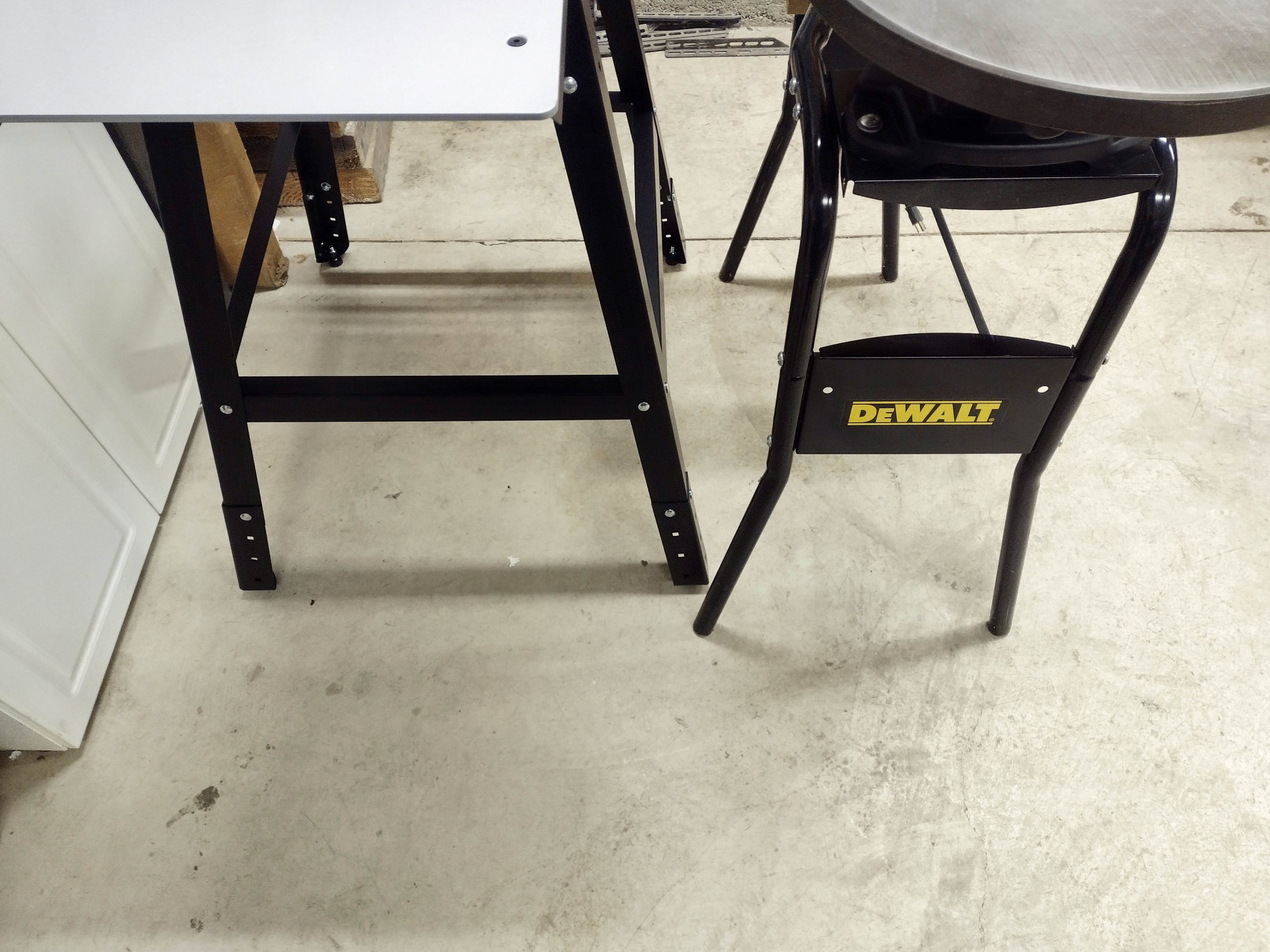
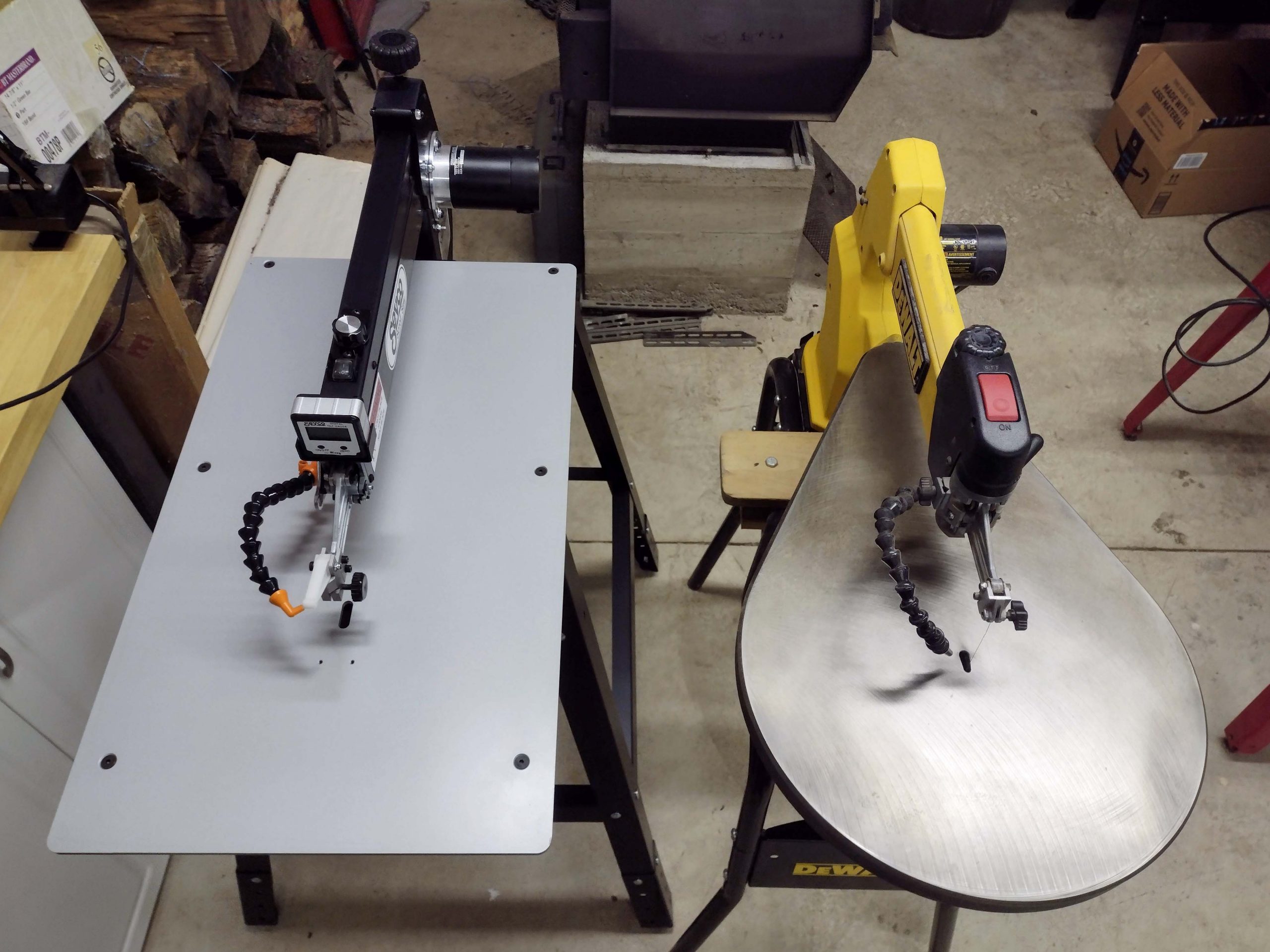
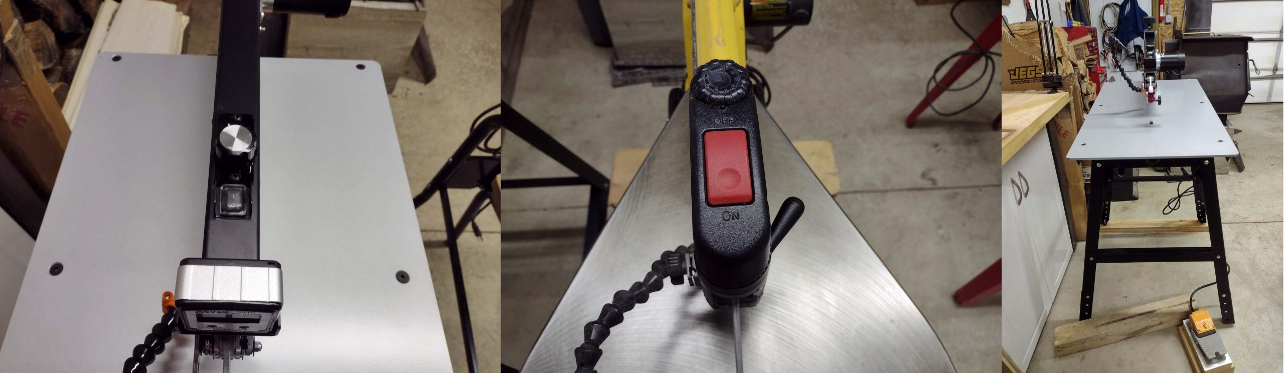
Line up of three saws
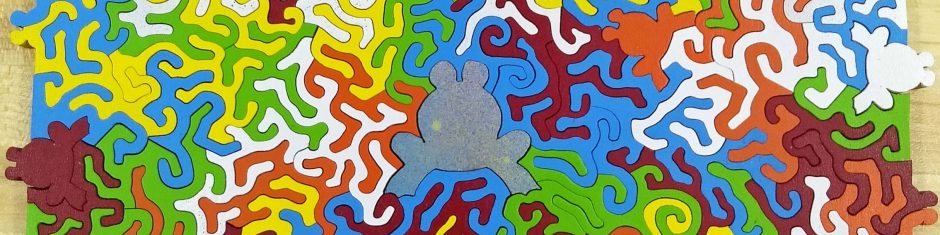
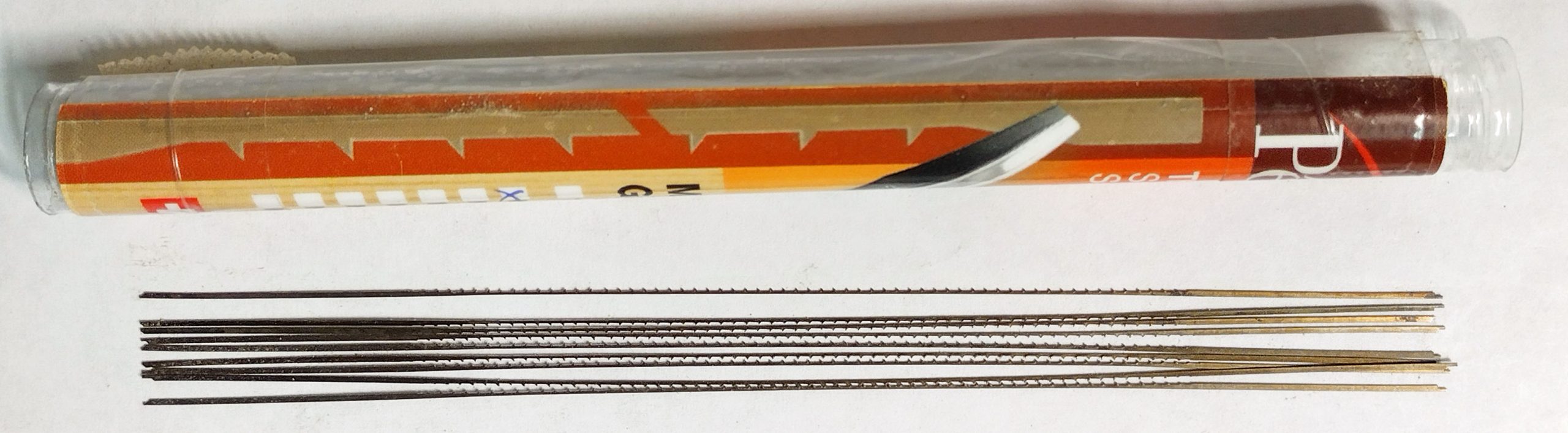
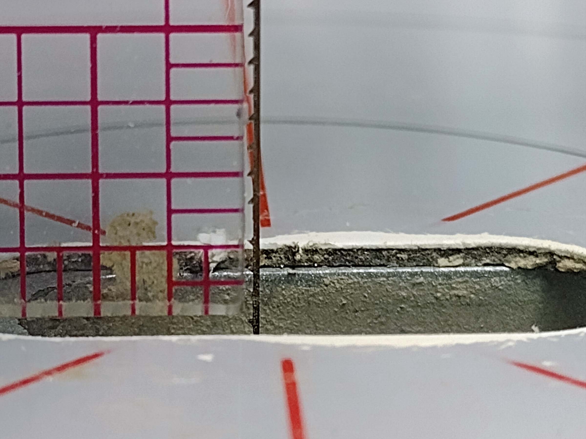
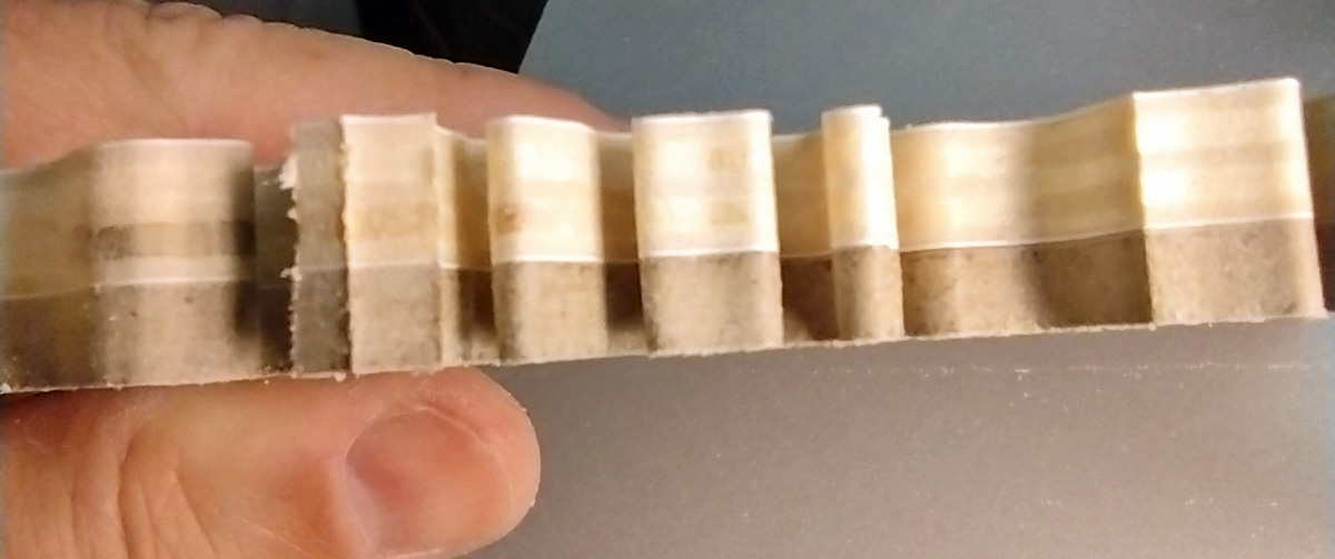
Which gets me to my gripe! My preferred blade for puzzle cutting is the Pegas MGT 2/0R. Once installed in the saw, it performs the best of any blade I have used for puzzle cutting. However, they are not all the same length in the same batch! Very frustrating! Look at the next couple of pictures. I have some loose blades on a piece of white paper. I used a metal straight edge to align the left side of the blades. Look at the right side!
Pegas MGT 2/0R blades
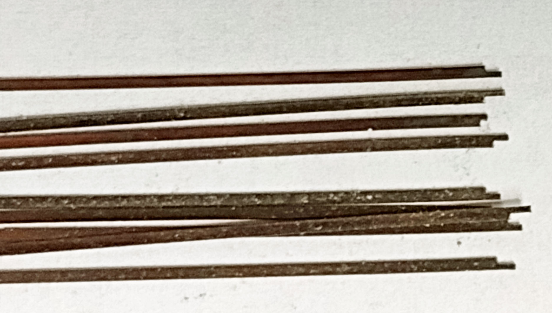
Close up of the same image showing the variation in length
1/16″ difference in length
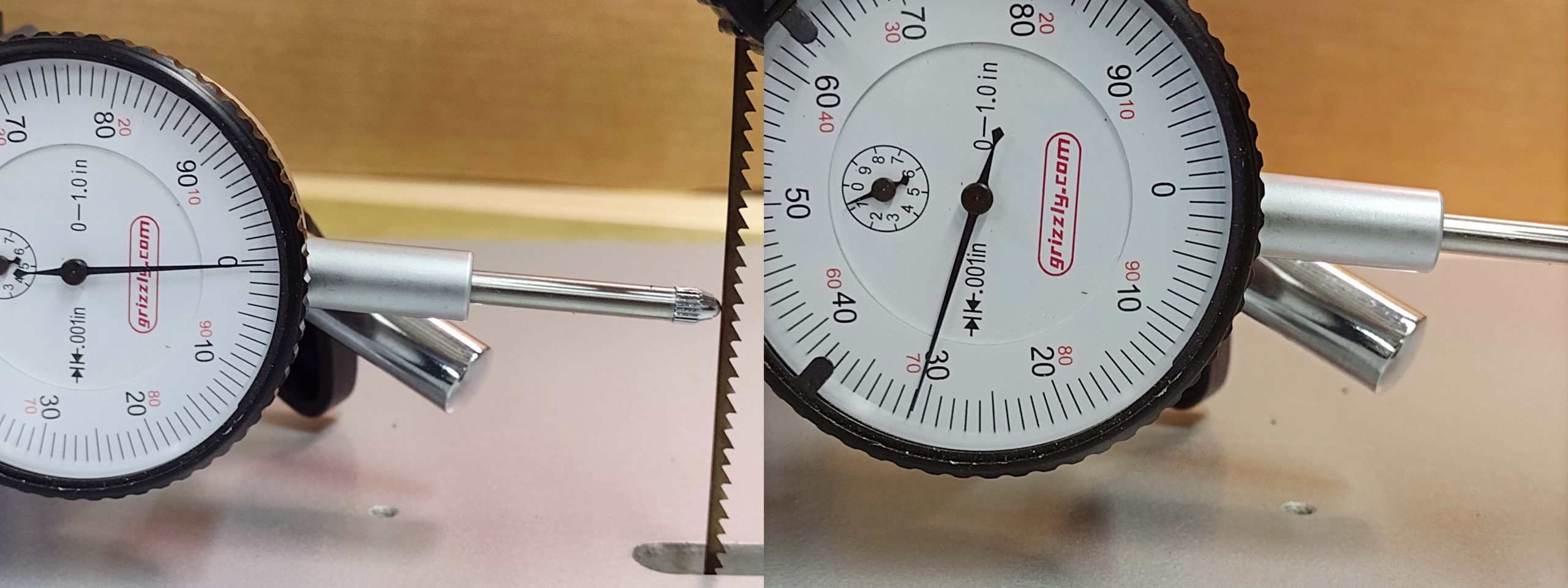
The next two photos show the effect on blade tension. The first one shows the long blade, the second shows the shorter blade. This is without adjusting the tension, it is just from the difference in blade length.
Tension with long blade
Tension with short blade
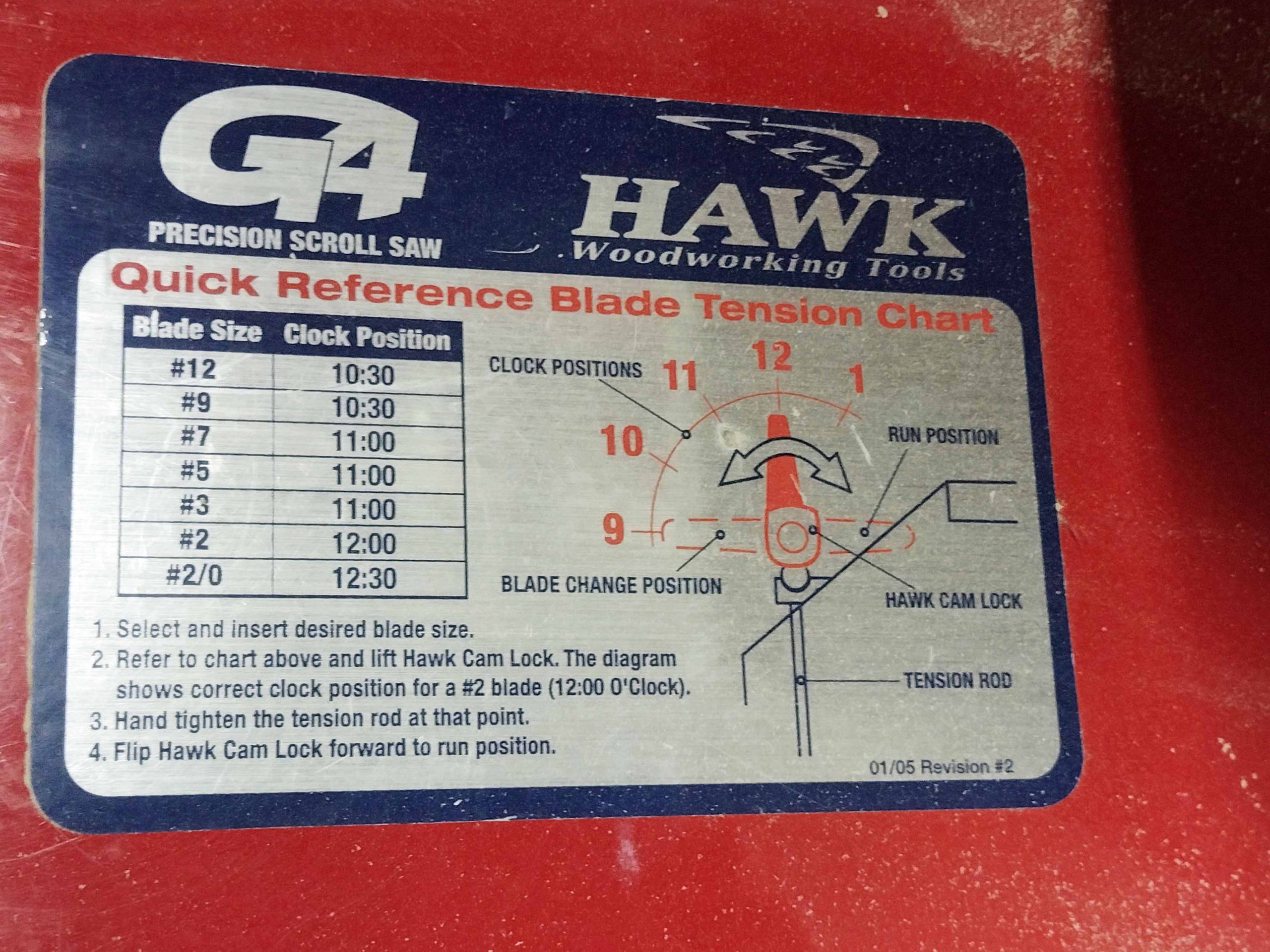
Here is an image of the chart showing proper tension adjustment by blade size.
Blade Tension Chart
I ended up resolving this with a wire cutter. I drew two parallel lines on a piece of paper based on the shortest blade in the pile of blades. Every time I installed a blade, I cut it to length so that I had uniformity in blade length. This worked like a champ, but I don’t think I should have to do it!
Blade length gauge
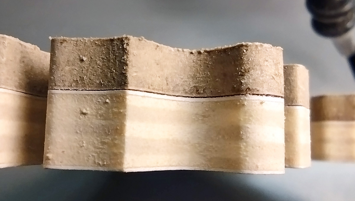
I thought perhaps I had a bad batch. This batch was bought April 4, 2024. I had two newer batches, so I checked them as well. Here’s a sample from the batch bought September 9, 2024.
Batch bought in September 2024
The discrepancy was even higher being 3/32″!
3/32″ length discrepancy
Here’s a batch bought just a couple of months ago.
Batch bought April 17, 2025
And what’s with the little nibs on the end of the blades? Some of the nibs are long enough that they are part of the surface area the blade clamp screw engages with. None of the other blades in my possession have those, they are all cut square.
Some other manufacturers seem to be better on uniform blade lengths. Here are some examples.
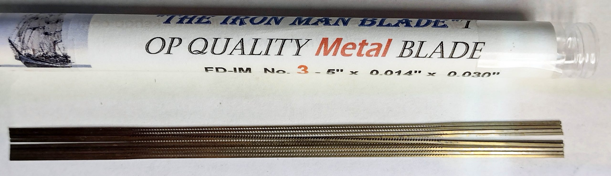
Flying Dutchman Iron Man Metal Blade #3
Flying Dutchman Scroll Reverse #3
Flying Dutchman Two Way Cut #2/0 – a little bit of variation
Flying Dutchman Ultra Reverse #1
Olson Universal #7R
Even other Pegas blades are better in uniformity and do not have the nibs on the ends.
Pegas Double Skip 2/0
Pegas SPR #3
Some of the others are not uniform in length.
Olson Universal #2R
Olson Universal #9
Seyco 5-D
This was never an issue to me before because of the blade clamp mechanism of the parallel link saws. Now it is an issue because I want to take advantage of the better control from the parallel arm saw. It seems like everything is always a compromise. I find the Dewalt blade clamp/tension system the quickest and easiest to use, but the front to back motion of the blade seems excessive as compared to the Hawk.
I have no real solution to this other than to change the blade I use or keep cutting them to length. As I like the way they cut, I will keep cutting them to length when I use this saw.
Hopefully this is interesting to those who read it.
Check out my Etsy store for puzzles for sale. It will be a couple of months before any new ones are posted. I have a back log of custom puzzle orders to get through.
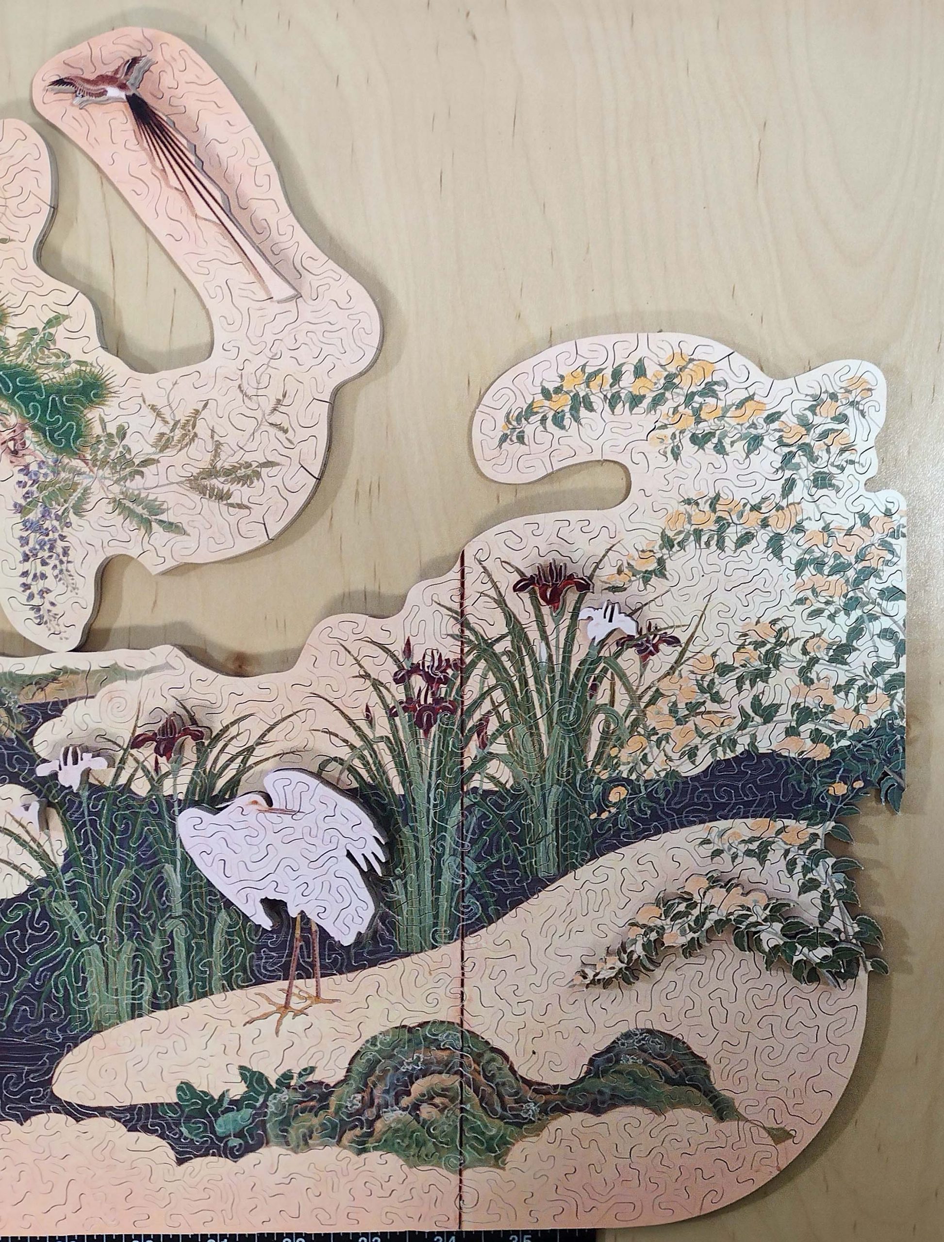
In October 2024, a customer and I started discussing options for a larger version of a puzzle I previously cut. This was “Birds and Flowers of Spring and Summer” by Kano Eino. Having been painted in the late 1700’s, the image is in the public domain and digital files of it are available from several sources. We finally settled on a puzzle size that would require four 13″ x 19″ prints to make it happen! The puzzle was to be approximately 18″ x 42″, have an irregular edge, and be around 830 pieces. As you will see, I way overshot on the piece count.
There are two major factors that limit how big of a puzzle can be cut. The first one is how large of a printer you have. My printer will print up to a 13″ x 19″ image. You can merge these along an edge to make a bigger puzzle. I have written articles on this process before. The second factor is how big of a piece of wood can be cut to the center of by your saw. In my case, I have a 26″ saw. This meant that I could print something 19″ tall and make it as wide as I want to by merging or joining multiple prints side by side.
In late March, I was finally ready to get started. The first step was to print the images I needed. Here are the four prints I used.
Four prints to be merged to one.
I did have some printer issues. It may be time to replace the trusty printer I have been using for 13 years. Some of the prints had an issue with color matching, even after cleaning the heads and replacing the ink. In the picture below, you can see the problem I was having. It took about 4 attempts and some fudging on what was printed to make the colors match. But now I do have some left over prints that I can use for future smaller puzzles!
Color matching issues.
The four prints were mounted on cherry Appleply. They were then cut into two sections lengthwise using my 26″ Hawk scroll saw.
Printed and mounted panels cut in half lengthwise
These were then double stacked, glued together, and cut to merge the pieces.
Double stacked and ready to make merging cuts.
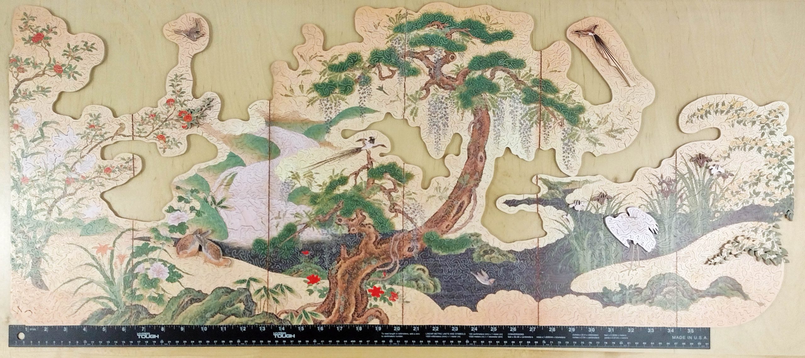
Then they were fit together and the irregular edges cut. The puzzle is 41″ long and up to 17″ tall.
Merged together and irregular edge cut
There was a lot of waste on the floor to this point.
Waste and debris
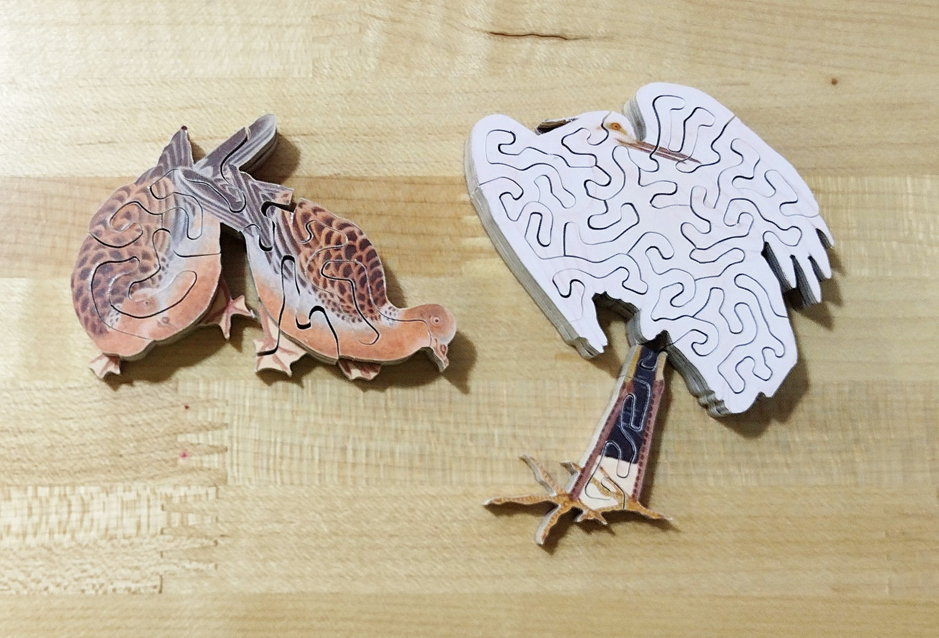
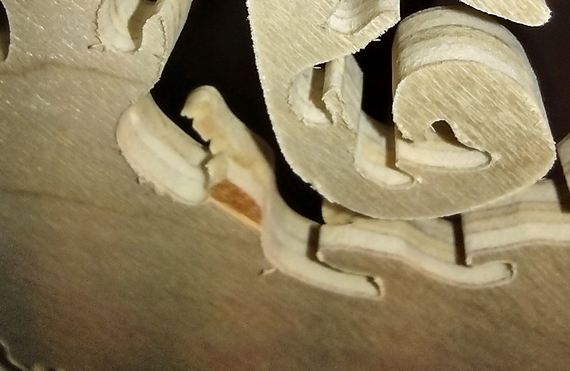
I decided to use some of the birds and flowers from the extra prints to make thicker pieces. I cut them out with scissors and mounted them on pieces of the waste plywood shown above. I then cut them out using the scroll saw and glued them in the appropriate places on the big puzzle. Here is an example of one of the birds and a couple of flowers. You can also see part of one of the merge cuts where two different panels were joined together.
3-dimensional bird and flowers
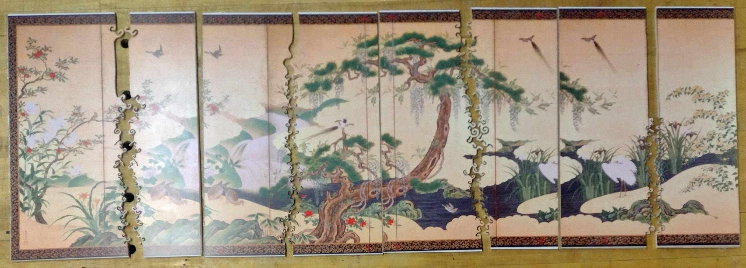
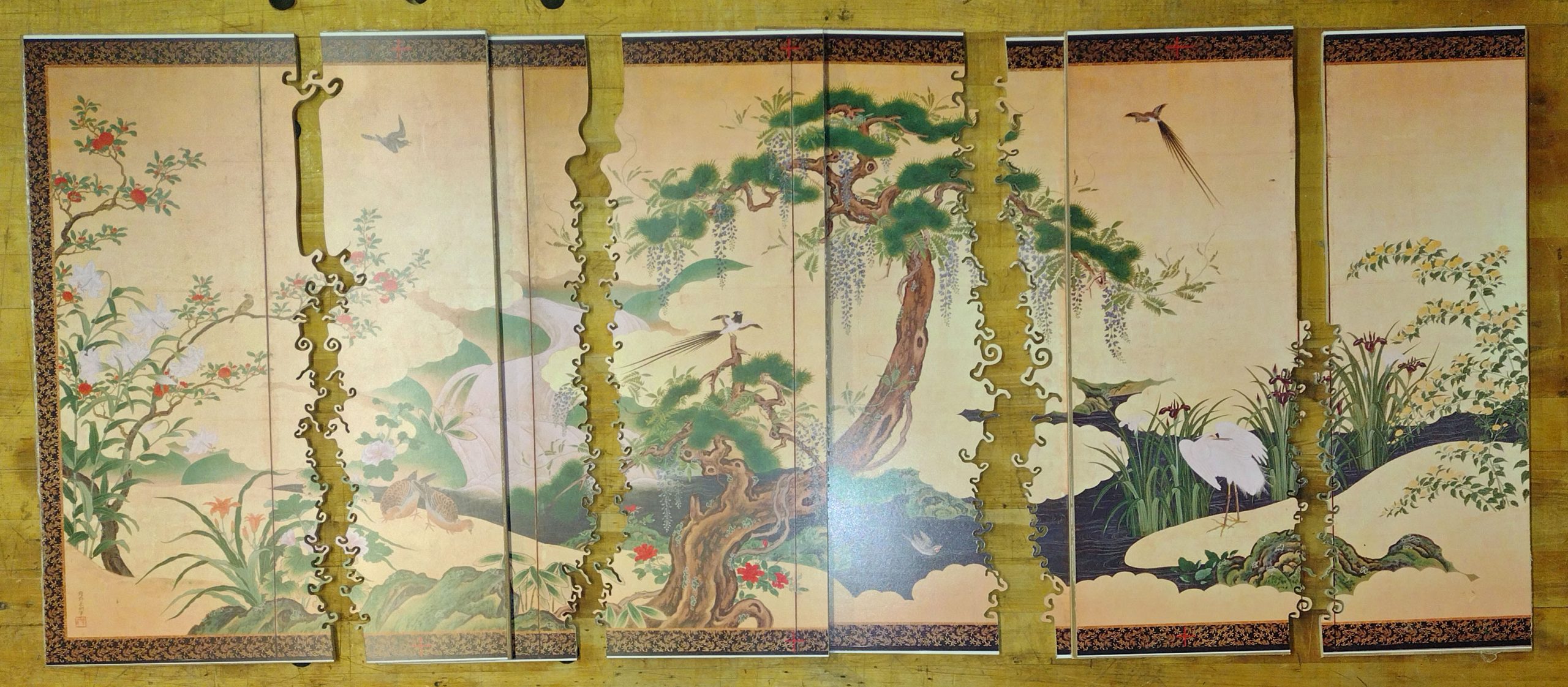
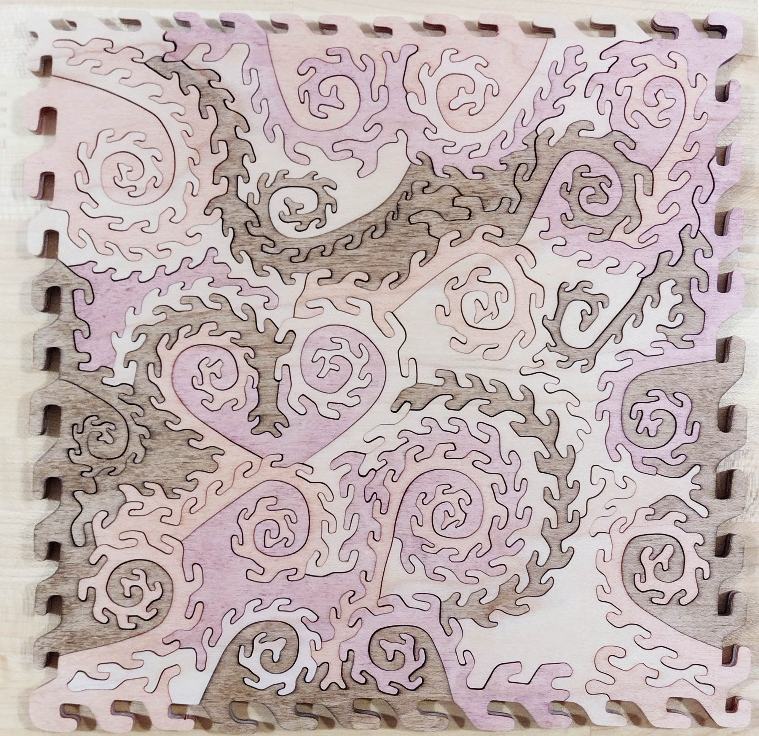
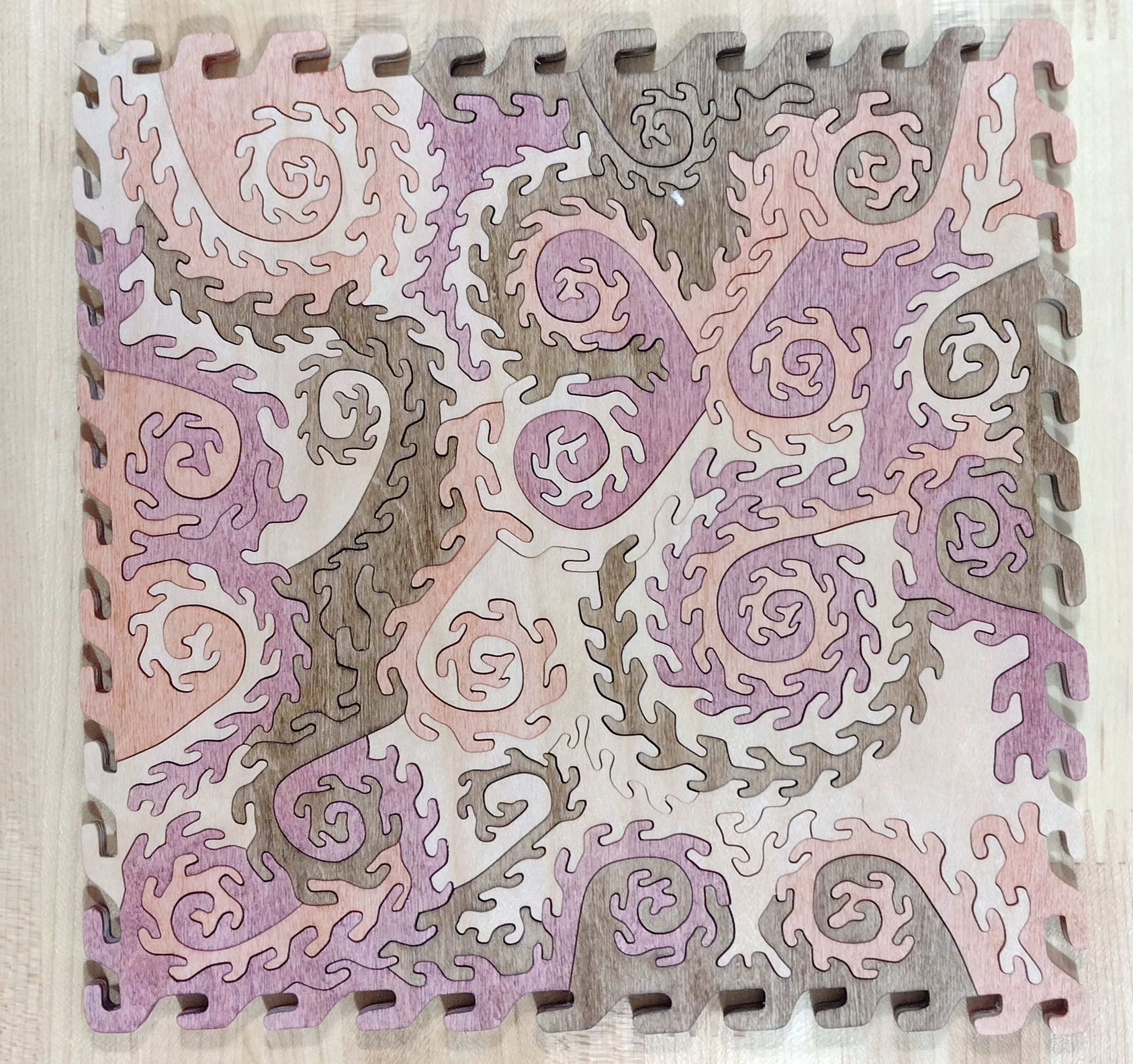
Next came the regular cutting of the puzzle. Some pictures of the puzzle follow below. First is an overall shot of the front of the finished puzzle. You can see there are a few locations with the thicker pieces. I also did a little more irregular edge work on the right side.
Front of the finished puzzle
More detailed view of left side.
More detailed view of center of puzzle
More detailed view of right side.
There are 27 figurals/special pieces, some of which are further cut into smaller pieces. Some of these are just color line cut images from the painting, some are figurals that actually come from some of the artist’s other paintings, and some are the thicker 3D pieces.
For some reason, I am pretty tickled by the 3D birds with the feet showing on the thinner sections.
3D birds
More 3D pieces.
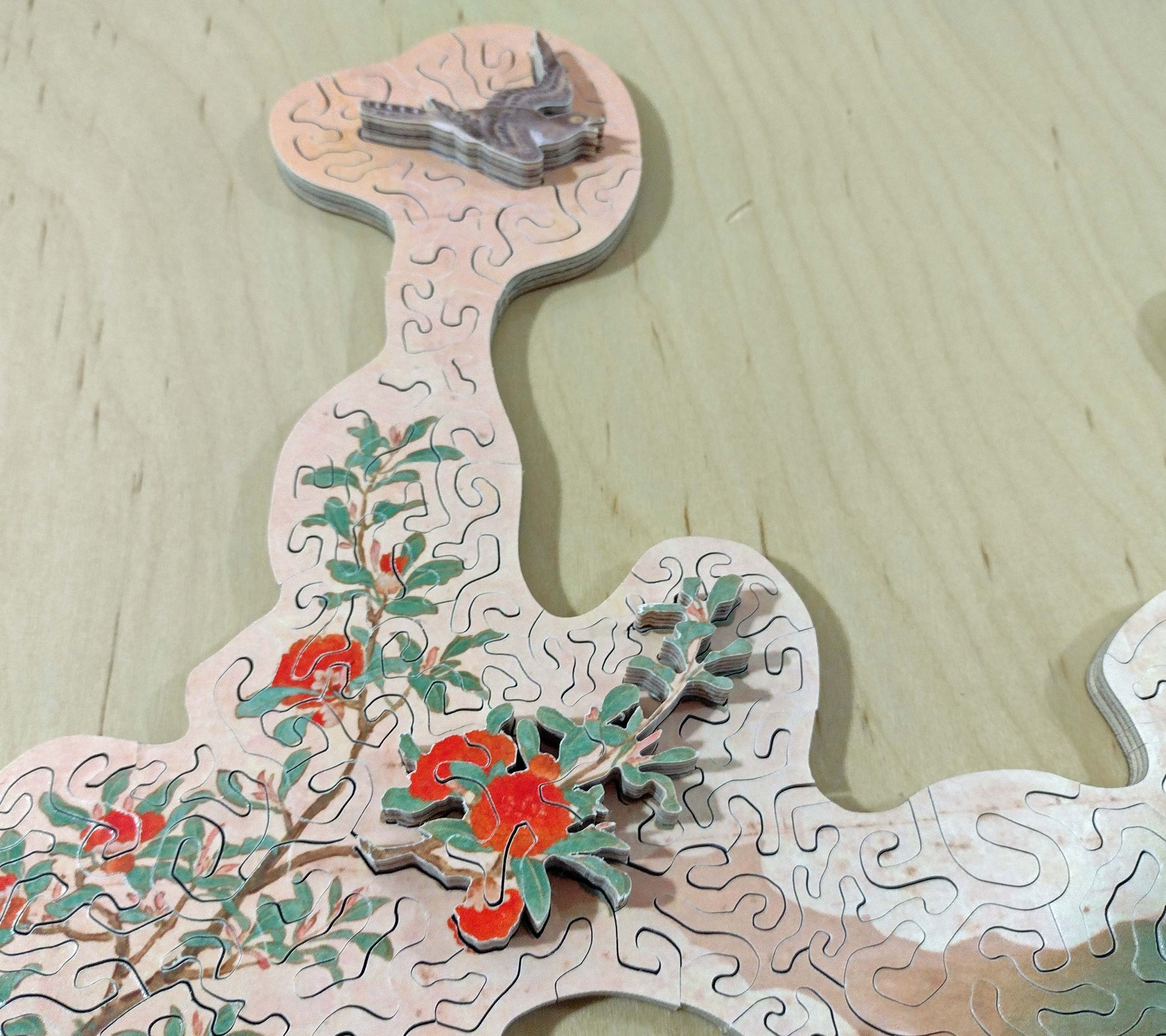
Soaring bird and branch sticking out
Here is a shot of the back of the puzzle. You can see the thicker pieces protruding out.
Back of puzzle.
There were 118 stacks of ten puzzle pieces plus one stack of six. Additionally, there are two extra pieces thrown in that do not actually fit in the puzzle. 1186 puzzle pieces plus 2 more.
Stacks of puzzle pieces.
1186 pieces spread on the work bench
Between other activities, springtime yard work, graduation ceremonies, helping youngest son move, etc., it took until June until I was completely done with the puzzle. (If you think “retired” means lots of free time, think again!) I just finished the final counting this evening. 1186 pieces! That is a long way from 830! The customer is getting a nice bonus. She does not want this shipped until later in the summer, but said to go ahead and make a blog write up if I wanted.
It has 528 square inches as determined by tracing it on graph paper and counting squares. That gives about 2.2 pieces per square inch. One of my normal boxes will not hold this puzzle, so I will have to find a nice one at Michaels or Hobby Lobby.
If I had not cut away so much of the clouds and sky, this puzzle would have had around 715 square inches. At the same piece density, it would have been around 1600 pieces.
What more is there to say? I cut this entirely using a Hawk G426 scroll saw. In the process, I absolutely fell in love with using this saw. I have had it for a number of years but did not use it a lot. There is a learning curve, but once you meet that curve it is an awesome saw. I previously wrote a blog article on how I had to make an auxiliary table so that I could use my preferred blades with it. While cutting this puzzle, I found out there is another issue with using my preferred blade. That will be another blog article shortly.
So why do I like this saw so much? Because of its cutting action. It is a constant tension parallel arm saw. Because of the geometry of the blade motion while cutting, it has minimal back and forth blade movement as compared to the parallel link style of saws such as the Dewalt, Pegas, Seyco, Excalibur, etc. Significantly less movement. This makes the cutting action feel much more controlled. I played around with some of the extra pieces of scrap from this puzzle and was able to make some amazing delicate cuts that I could not duplicate on my Seyco without turning the saw speed waaaay down.
I corresponded with John Stokes on this issue. He used a 30″ Excalibur saw to cut his large panels to a manageable size. The Excalibur saw uses the parallel link mechanism. He says he ran that saw at very slow speeds to avoid disasters because the cutting action was too aggressive. He referred to it as a “rocky motion”, but I think that is referencing the amount of back and forth the blade travels. Once the panels were cut to a smaller size, he switched over to his 18″ Hegner saw for more control. The Hegner is another parallel arm mechanism like the Hawk. Because I had not really used the Hawk very much, I did not realize what a difference it makes while cutting.
So, there you have it. My largest puzzle to date and perhaps the biggest I will cut. But another future customer may want a big puzzle, so who knows?
Watch my blog for another entry soon on variations in blade length of scroll saw blades and possible impacts to the cutter.
Happy Puzzling!
Posted inCurrent project|Comments Off on Large “Birds and Flowers of Spring and Summer”
My next two puzzles are going to be large ones once again. I have posted several articles about joining prints end to end to make larger puzzles than my printer or saw can handle. These have been done using 13″ x 19″ prints joined along the 13″ edge. These next two puzzles are going to be joined along the 19″ edge.
The second puzzle of the two is going to be four 13″ x 19″ prints joined along the 19″ long edges to make a puzzle that is about 40″ long and 19″ tall. This puzzle is a commissioned piece, and I want it to be cut right. So, the first puzzle is actually an exercise of techniques. Practice makes perfect, right? I do intend to sell it when I am done cutting it.
If I have cut puzzles with joined images before, why do I need to “exercise” my techniques? Well, primarily because of the length of cut. In the past, I have started by cutting the puzzle board in half along the 13″ width, leaving me with two boards that are roughly 13″ x 9.5″. These are easy to work with. But by joining the 19″ lengths, my usual saw will not work because there is not enough room to move the wood around. I will have to use my RBI Hawk G426, which has a 26″ throat depth. As discussed in the previous blog post, I had some concerns with cutting on the Hawk. These have been addressed, so I am ready to roll.
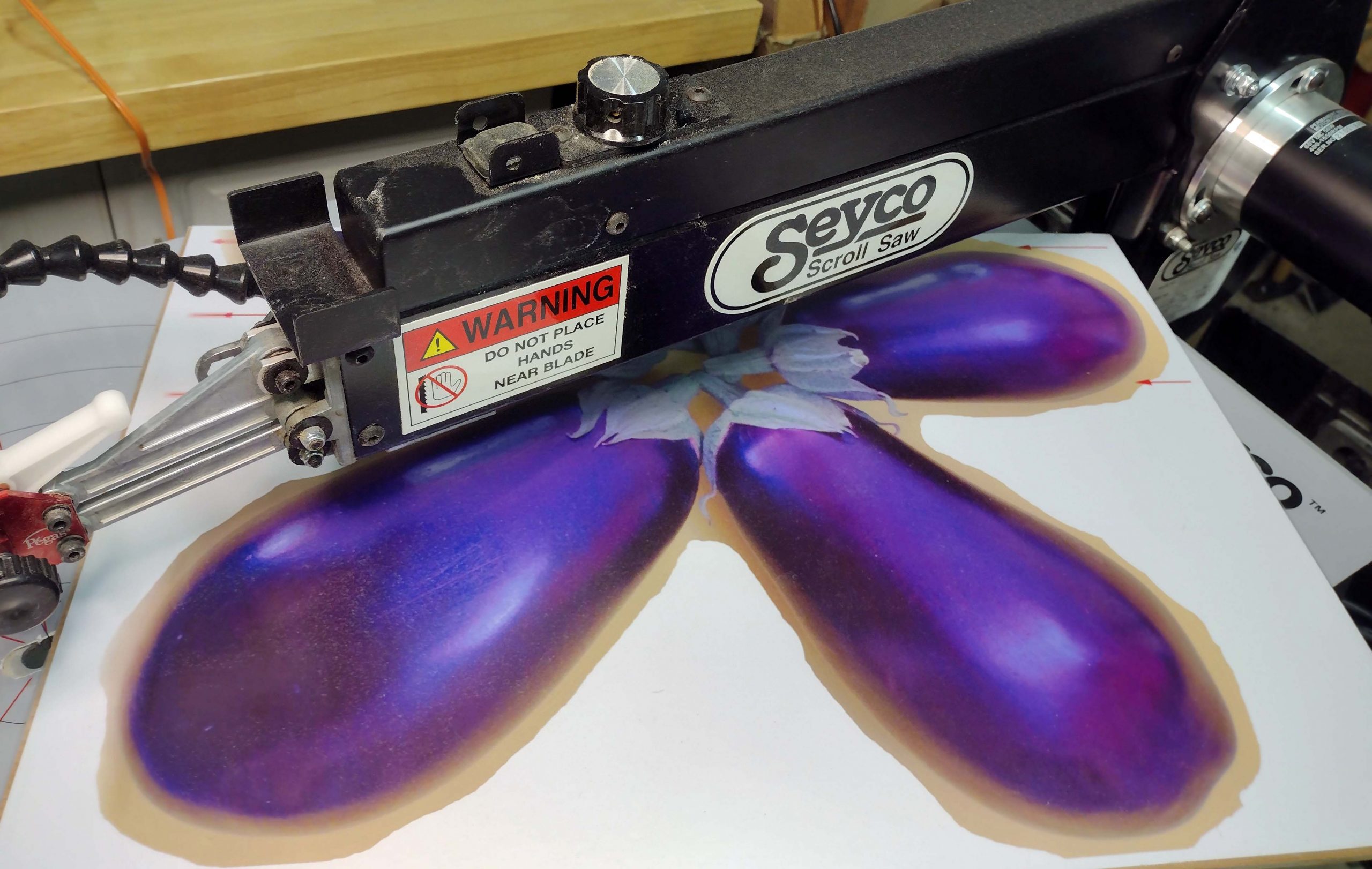
This first puzzle is going to be one of my popular eggplant flower puzzles. I have made these in the past using prints on 8.5″ x 11″ and on 13″ x 19″ paper. The smaller ones of these have about 30 square inches, and the bigger ones have about 92 square inches. I am going to make one from two 13″ x 19″ prints joined together, which should have about 200 square inches when done.
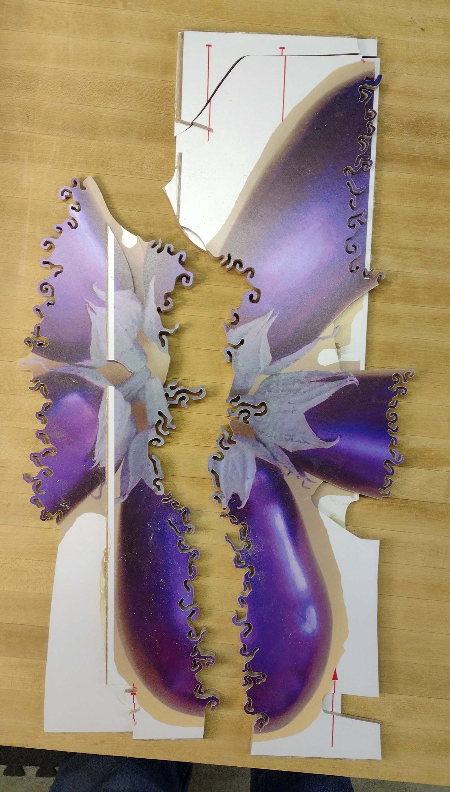
Here are some pictures of the two prints. You can see the red lines and arrow heads I printed in waste areas of the images to help with alignment while stack cutting.
Two 13″ x 19″ prints to make one puzzle
Two prints stacked up like they will be
The first steps are to cut each print in half the long ways to make it easier to handle the pieces. The difficulty with this is that the saw I normally use does not have a large enough depth of cut. The Seyco has a 21″ throat on it. My old DeWalt had a 20″ throat. If you take a 13 x 19 rectangle, the hypotenuse is 23″. It just will not fit.
Too big to fit
Now, you can argue that if you cut the board in half right in the middle down the 19″ length, the hypotenuse is just over 20″ and therefore I could do it on the Seyco. That really does not leave any room for comfort, though.
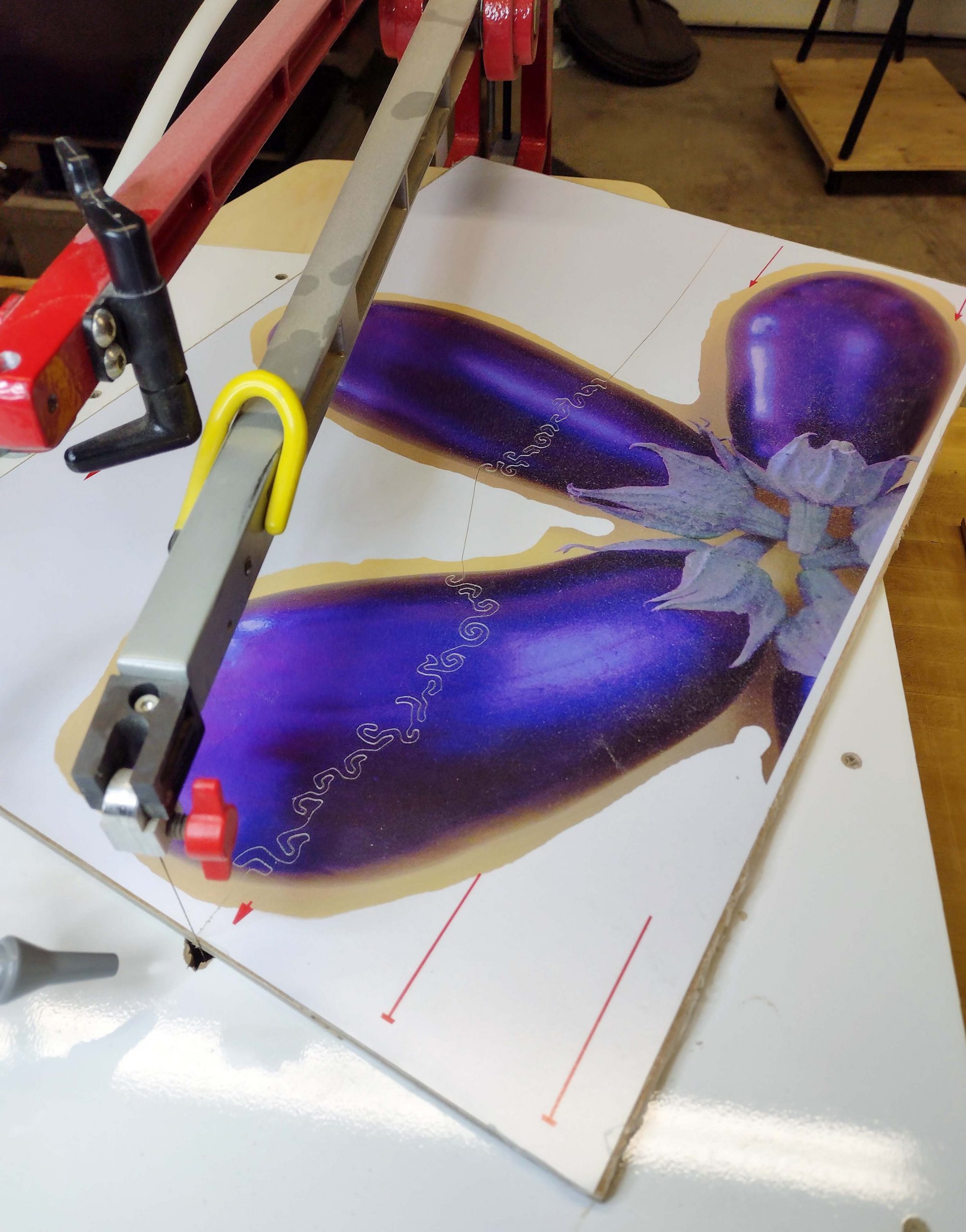
Here is the first board being cut in half on the Hawk. It is done. There is plenty of room at the back of the saw for swinging the board around.
First board cut in half
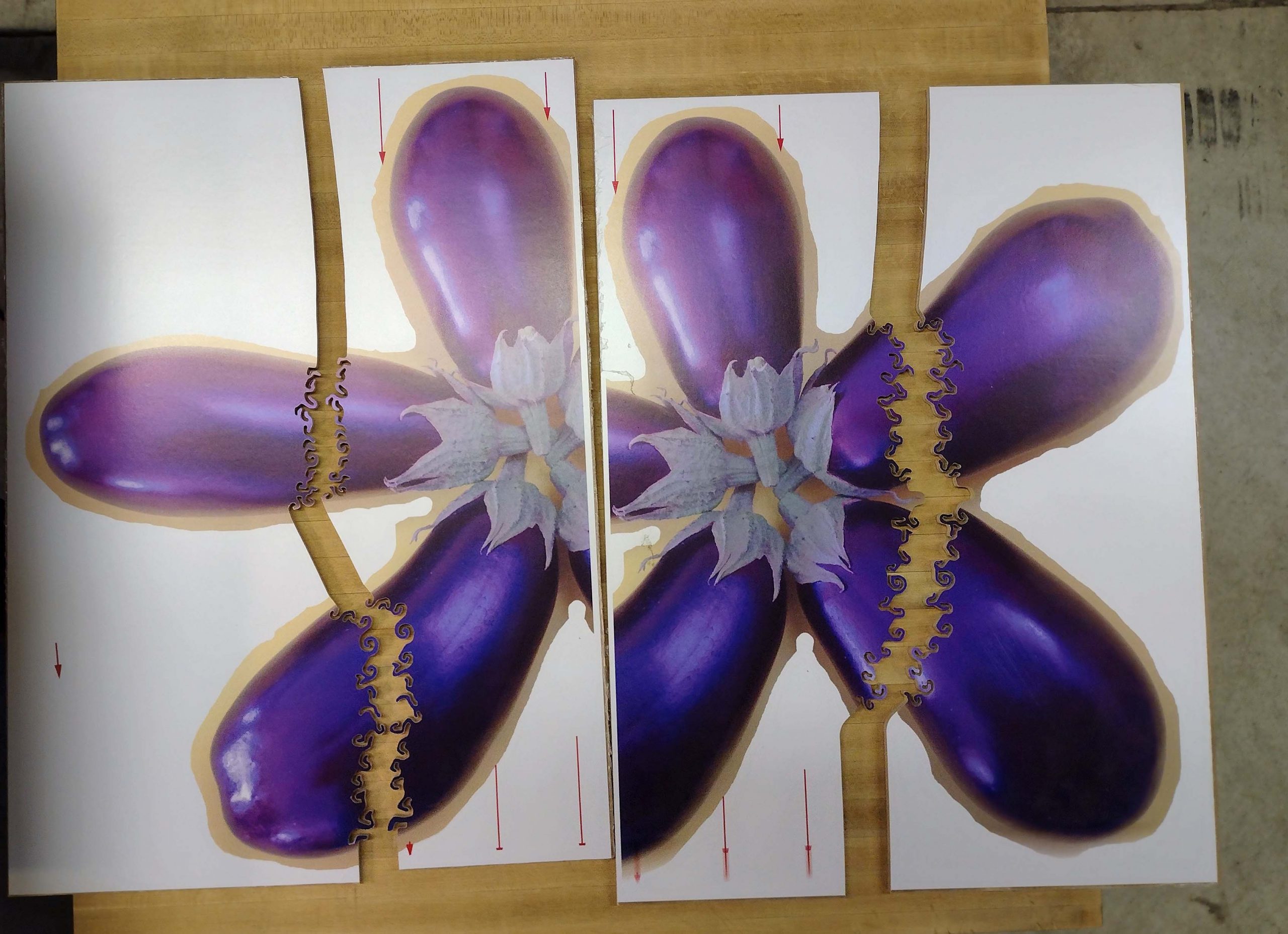
Here are both boards cut in half.
Both boards cut in half.
Next is to line up the middle two pieces, glue them together and stack cut them.
Middle pieces stacked up
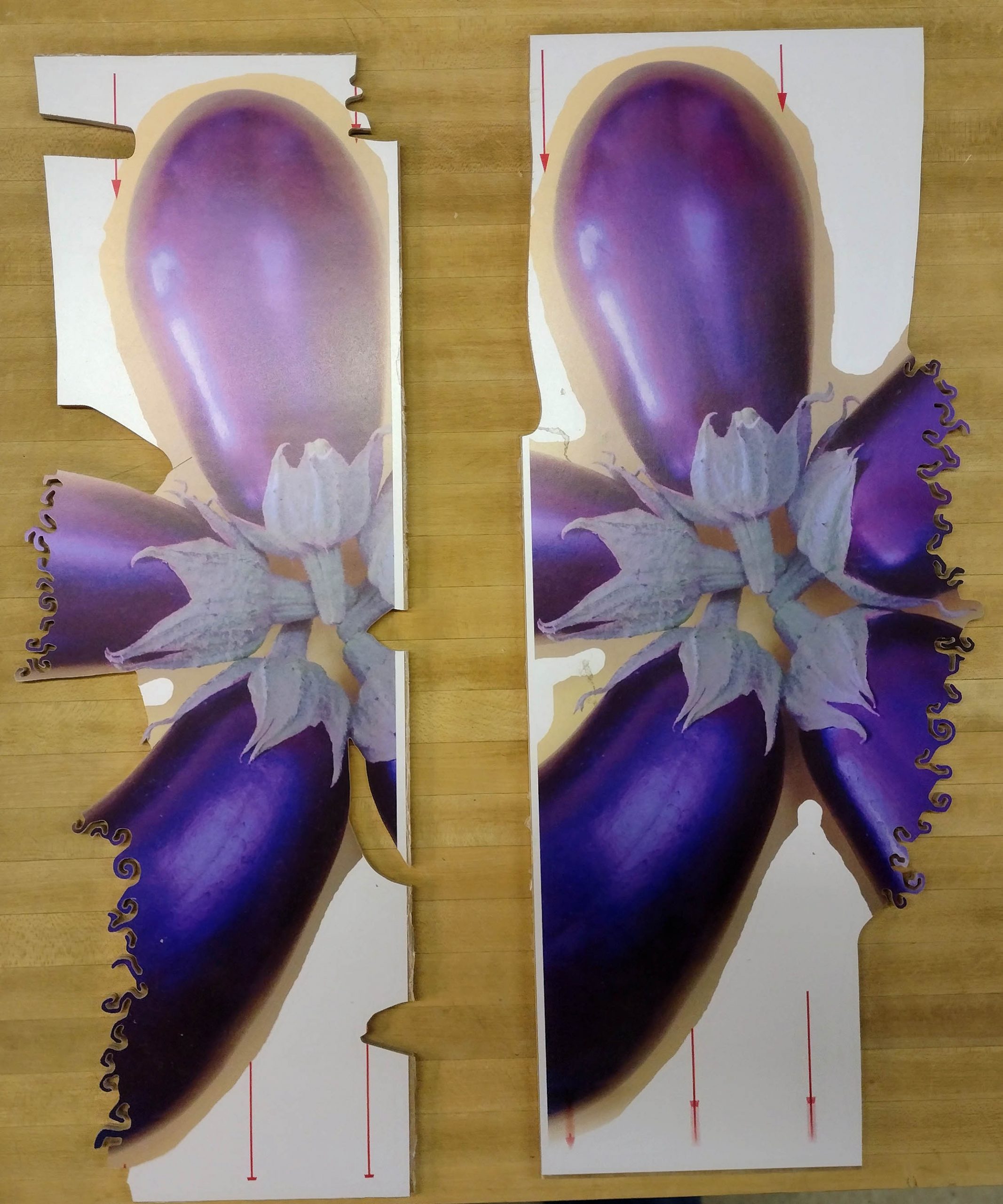
Notches are cut in the one board to allow for alignment to the other board.
Notches cut in left piece for alignment
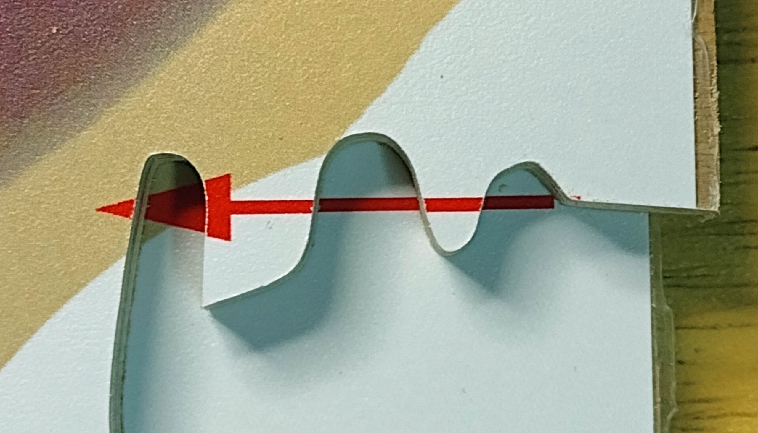
Example of alignment
One alignment mark looks good.
More alignment
Leaf on top piece perfectly aligned with bottom piece
Once the panels are perfectly aligned, glue them together with hot melt glue in a waste area that can be cut off later.
Line of hot melt glue in waste area
More glue
More glue
Start the double stack cut
Start the cut
Double stack cut complete
Double stack cut complete, ready to separate the pieced
Cut off the waste areas where it was glued.
Removal of glued waste areas
Now put the two different prints together.
Marriage line of two different prints
Cut off the excess waste around the other fruits and put the fruits together.
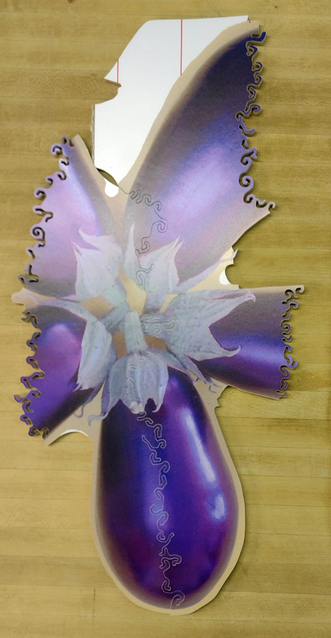
Rough eggplant flower, ready to finish cutting pieces out
Five petaled eggplant “flower”, ready to be cut into however many pieces. Some of the waste material remains around the fruits to allow for more hot melt glue in the event I decide to double stack again to make trick pieces.
This will be put aside to finish another day. Commissioned puzzles await and take priority. This one will be finished when they are all done. It will eventually be listed at my Etsy store.
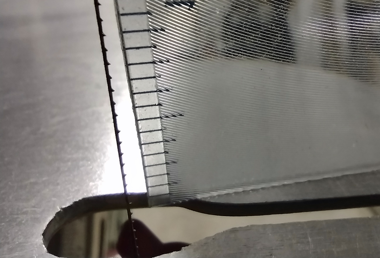
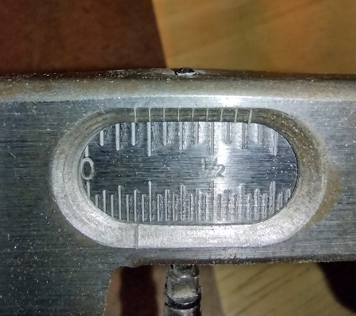
I am preparing to cut some puzzles that require the large depth of cut allowed for with the Hawk G426 scroll saw I own. You may remember from my prior posts on scroll saw comparisons that I had an issue with my preferred blade on this saw. Specifically, the reverse teeth section on the Pegas MGT 2/0R blades protrudes too far above the tabletop and results in a ragged cut of the image when using nominal 1/4″ thick material. Here is a picture showing the problem:
Blade at top of stroke on Hawk G426 scroll saw
The scale graduations are 1/16″, so you can see at about the 1/2″ mark where the reverse teeth switch over to normal downward pointing teeth.
To make this saw work for me, I needed to make an auxiliary table that raises the cutting surface. This would allow the reverse teeth to enter the bottom of the puzzle without continuing through to the top and tearing the image. This also gives an opportunity to make a slightly larger tabletop, which I prefer.
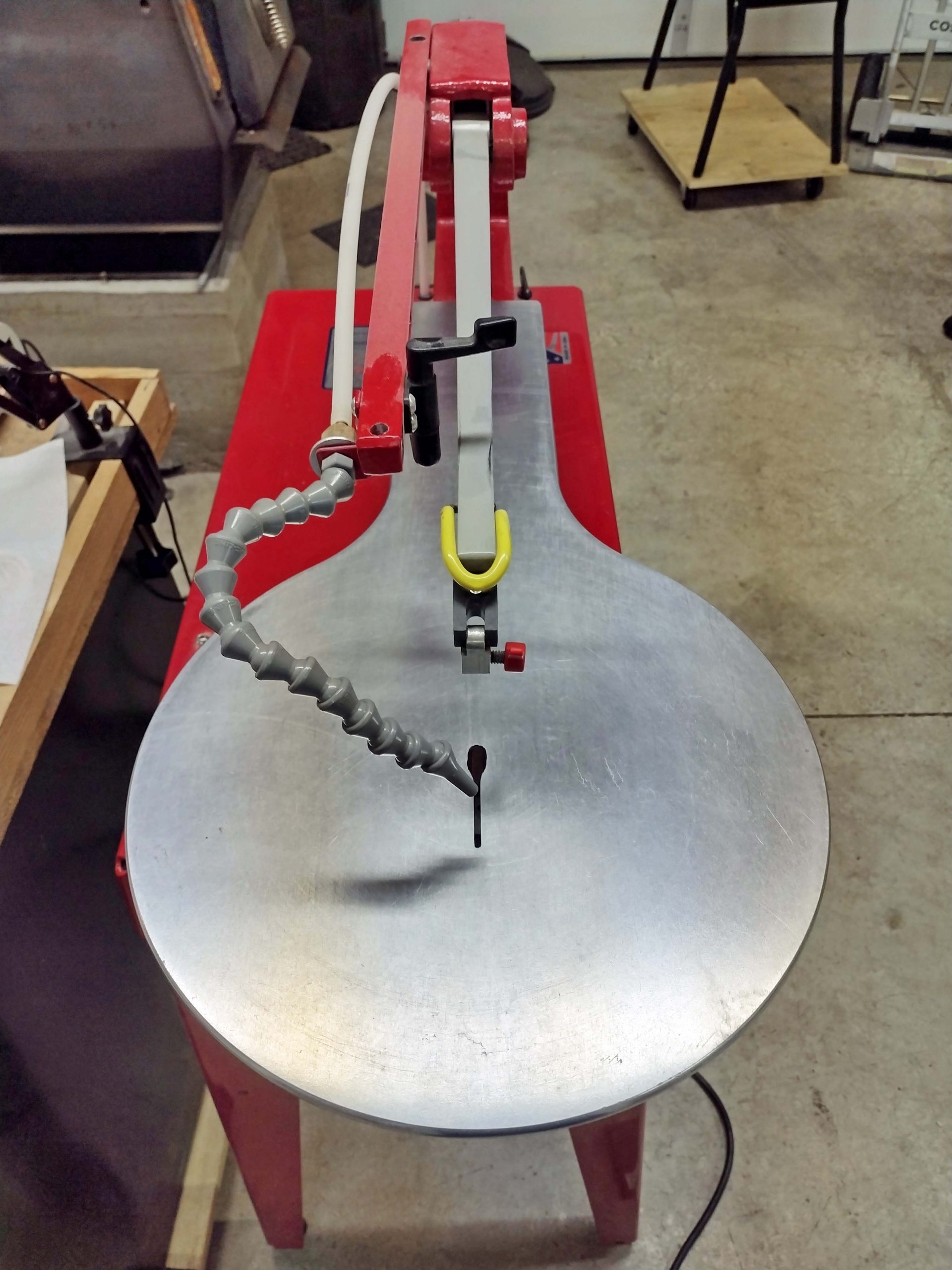
Here is the saw table by itself:
Factory tabletop on Hawk G426
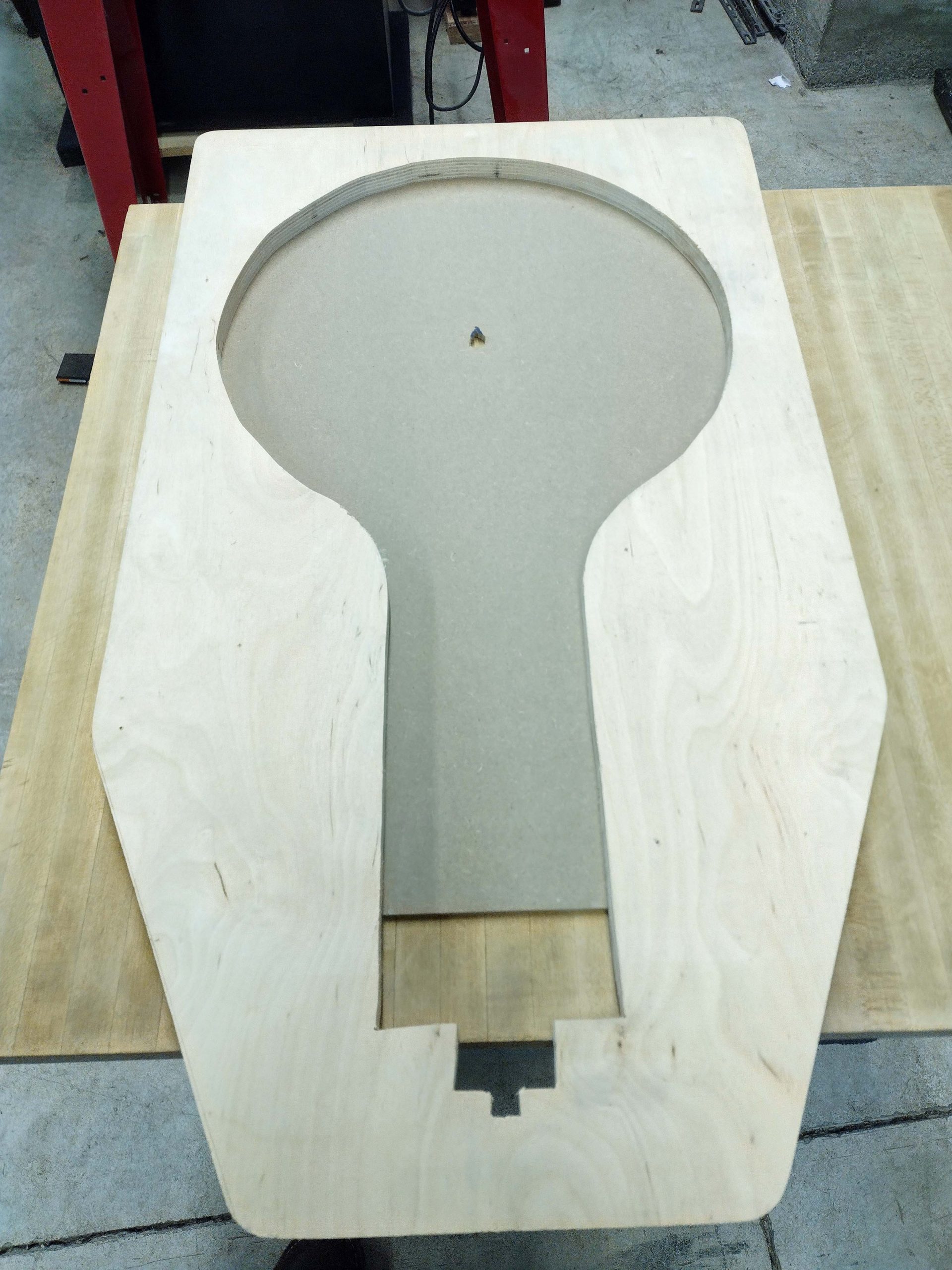
I made a tracing of the table, transferred it to a 3/4″ thick piece of scrap Baltic Birch, and cut it out to make a frame for the auxiliary tabletop.
Auxiliary tabletop frame
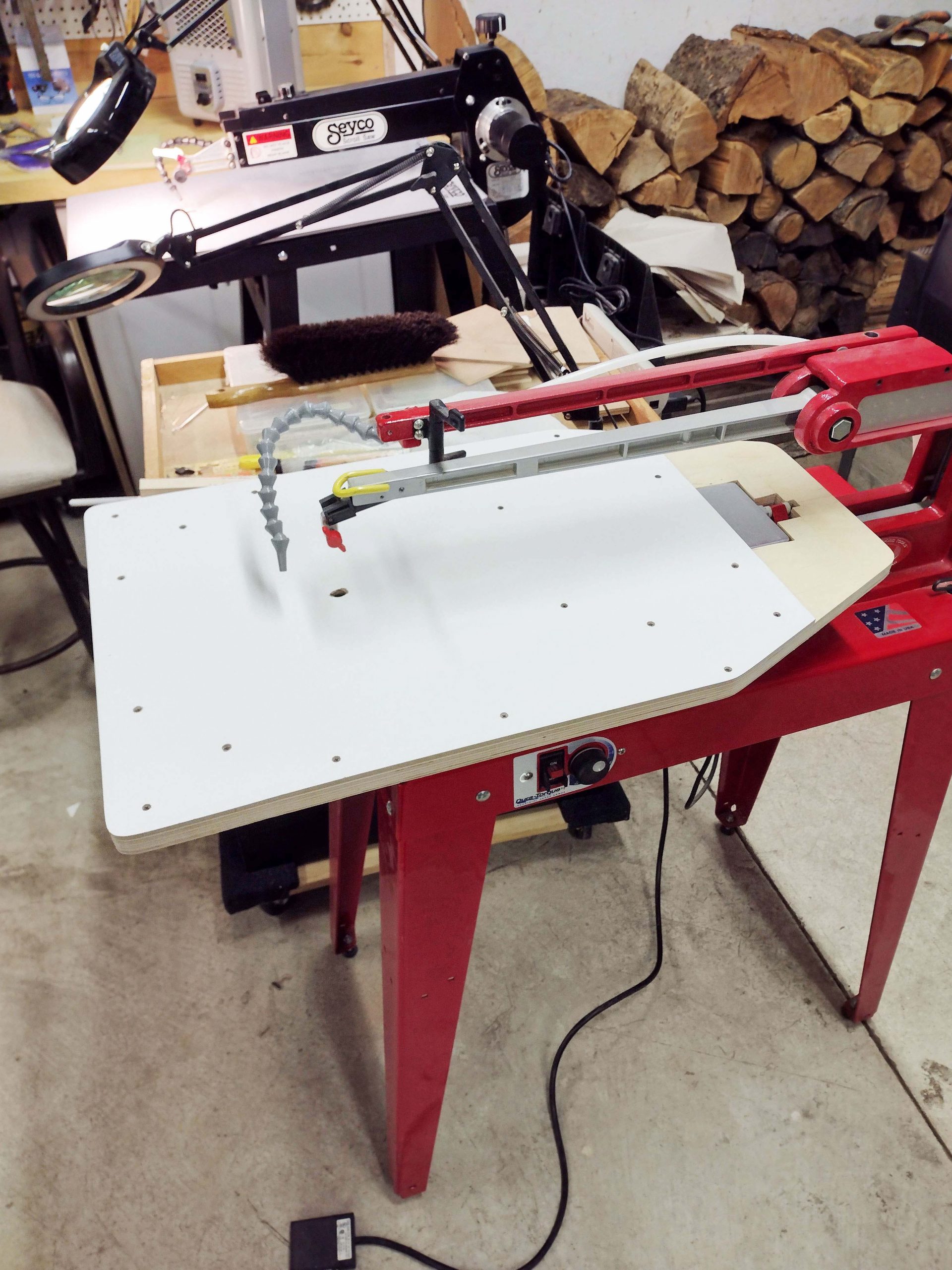
Next, I found some scrap material that is nominally 1/4″ thick and finished on one side with a slick material. I screwed this to the frame material and set it on the saw.
Saw with auxiliary tabletop on it
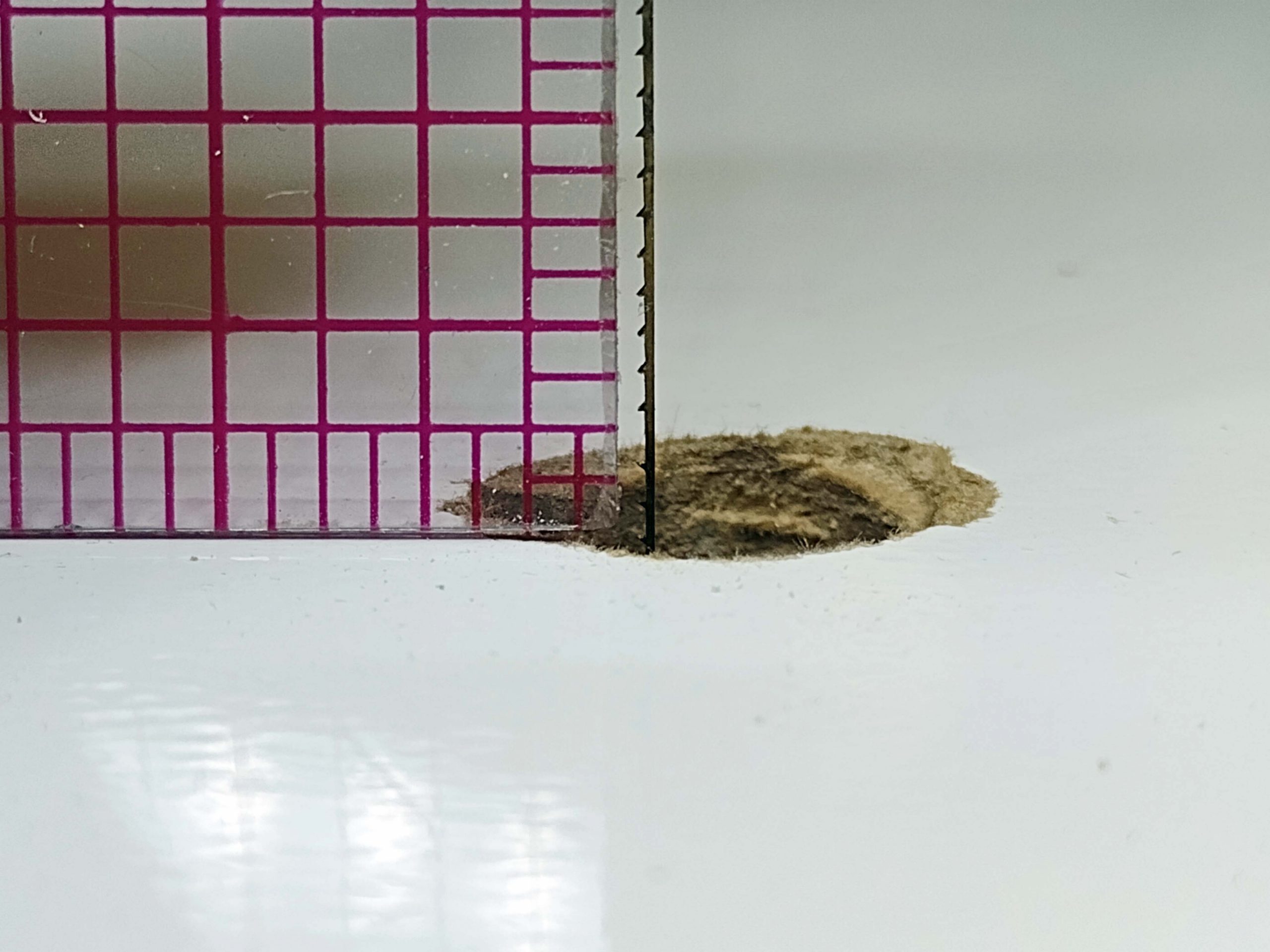
Next, I measured the length of reverse teeth blades projecting above the tabletop at the top of the saw stroke. You can see in the picture below that it is less than 1/4″. Perfect!
Less than 1/4″ of reverse tooth blade exposure
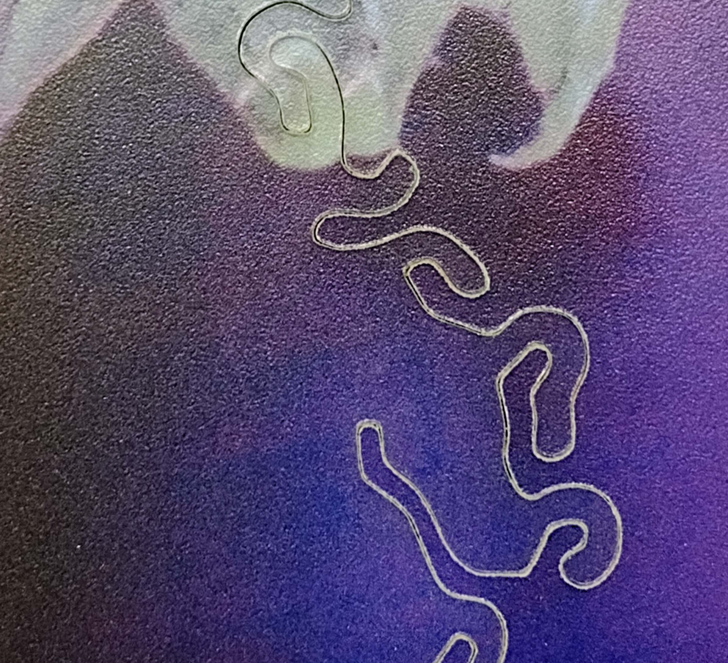
Dark colors are some of the most challenging to cut, as the saw kerf is very obvious. Here is the result from a dark purple image using the auxiliary tabletop. Not too bad, kind of what I expect with a dark color image.
Saw cut with Pegas MGR 2/0R blade while using the aux tabletop
Now, here is a cut with the very exact same blade while NOT using the aux tabletop. The cut on the left is without the additional thickness of the auxiliary tabletop. The cut on the right is with the auxiliary tabletop. The difference in cut quality is obvious.
Cut that results when reverse teeth protrude through the top of the image
Here is another view.
Another view of cut with reverse teeth protruding through the top
Since I like to experiment and document what I learn, here is a cut below using a Flying Dutchman Special Puzzle (FD SP) blade. A number of puzzle cutters use this blade, and it is what I originally used on my puzzles. It is a good blade and cuts pretty cleanly. I did not use the auxiliary tabletop for this cut, as the blade has no reverse teeth, and the extra table thickness makes no difference.
Flying Dutchman Special Puzzle blade on top piece, Pegas MGT 2/0R with auxiliary tabletop on bottom piece.
As you can see, they are pretty much the same cut on the top of the puzzle. I use them both, with the FD SP blades as my backup blade of choice. So, why do I prefer to use the Pegas MGT blades? Two reasons. #1. I cut other projects on my scroll saws, and I like to minimize the amount of sanding required. Reverse tooth blades provide a much smoother saw kerf on the bottom of whatever project you are working on. Here is an unsanded example picture of the bottom.
Pegas MGT 2/0R on the left, Flying Dutchman Special Puzzle blade on the right.
The cut on the left does not even really require any sanding.
The second reason I prefer the Pegas blades is because I feel I have more control over the cut direction. The FD SP blades are a little “softer” or something. When I move the wood to make a sharp turn, the blade tends to turn with the wood before “snapping” to the new direction. The harder Pegas blades tend to just stay pointed in the same direction, which results in a smoother flowing cut line for me. I have no problem using the FD SP blades, it is just a matter of preference.
Here are some other blades I tried with this sacrificial piece of purple image. You may remember from the double-sided pocket watch blog entries that I experimented with a number of different blades. The FD TC gave the best overall results for the double-sided puzzles without using zero clearance or sacrificial backings. And, since I like blades with reverse teeth on the bottom, here are the results with the Flying Dutchman version.
#1 – Pegas MGT 2/0R without the auxiliary tabletop (previously seen above)
#2 – Flying Dutchman Special Puzzle blade without auxiliary tabletop (previously seen above)
#3 – Flying Dutchman Two Way (FD TC) (2 teeth down, 1 tooth up, repeating the entire blade)
#4 – Flying Dutchman Scroll Reverse blade without the auxiliary tabletop
#5 – Flying Dutchman Scroll Reverse blade with the auxiliary tabletop
5 different blade results
The Flying Dutchman scroll reverse blade gives a decent cut as well. Here is the bottom side showing the results of those same cuts.
bottom side of the same cuts
Here you can see the FD Scroll Reverse blades are not as smooth on the bottom side of the cut as the Pegas reverse blades.
You can draw your own conclusions from my pictures. If you have not done so, I recommend you make a dark sacrificial test board to experiment with different blades on your own saw. Also check the relative position of reverse teeth to your tabletop on your saw if you use them.
With the DeWalt style blade clamps, you can adjust the position of the blade up and down between blade changes. If you do not consistently place new blades in the same position in those clamps, you can get erratic results of cut quality from blade to blade. With the constant tension parallel arm style saws, you generally have to fully seat the blades in the blade clamps and there is no adjustability with relation to the tabletop.
So now that I have my auxiliary tabletop and confidence in my saw blades, I can move on to my puzzle cutting challenge with larger puzzle boards. The next post will provide information on this.
Happy Puzzling!
Bob
Posted inTechnical|Comments Off on Blade Kerf Concerns
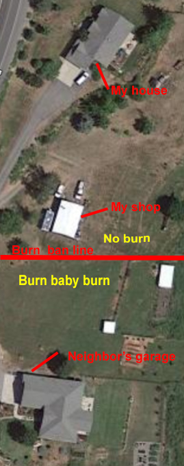
A while back, I mentioned in a post that I sometimes get frustrated by burn bans where I live. My shop is heated by a woodstove, and when air quality gets low, I cannot burn wood. My neighbor can, but I cannot.
Burn ban
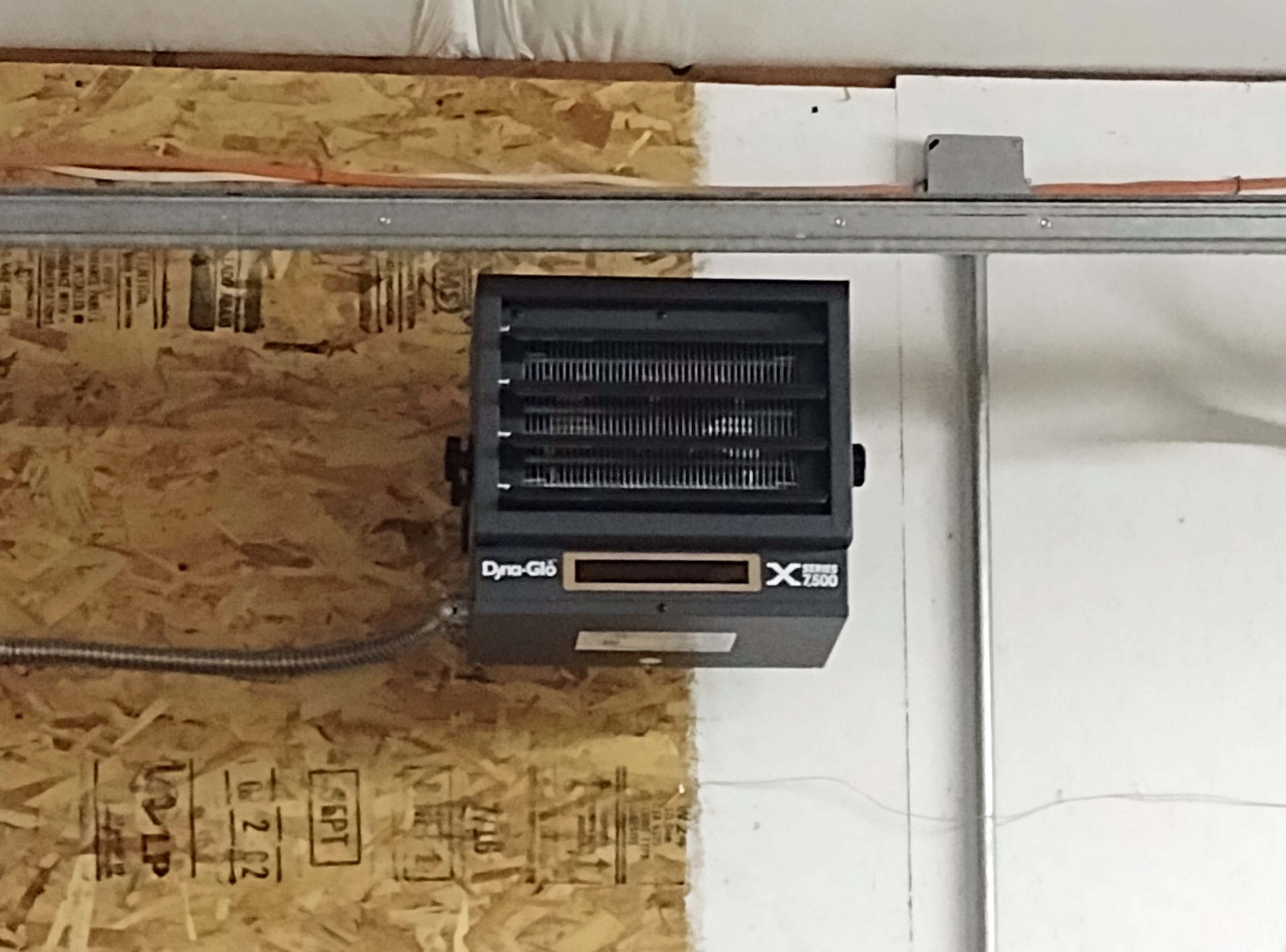
The only utilities available out of town where I live are electricity and land line phones. Installing a propane or natural gas or oil heater would require some expensive infrastructure installation. I don’t really care to have large fuel tanks on the property, nor loose much shop space to an inside heating unit. This summer, I had an electrician install an electric heater in the shop. I only have a 60-amp sub panel feeding the shop, so I was limited to a 40-amp load. (Upgrading to a 100-amp sub panel was cost prohibitive considering the distances involved.) That resulted in a 7500-watt heater mounted high up on the wall.
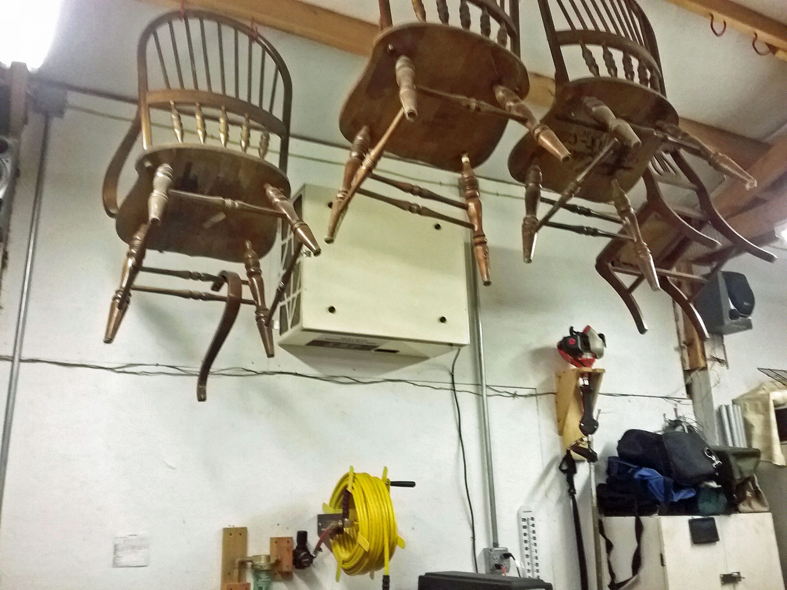
7500-watt electric heater
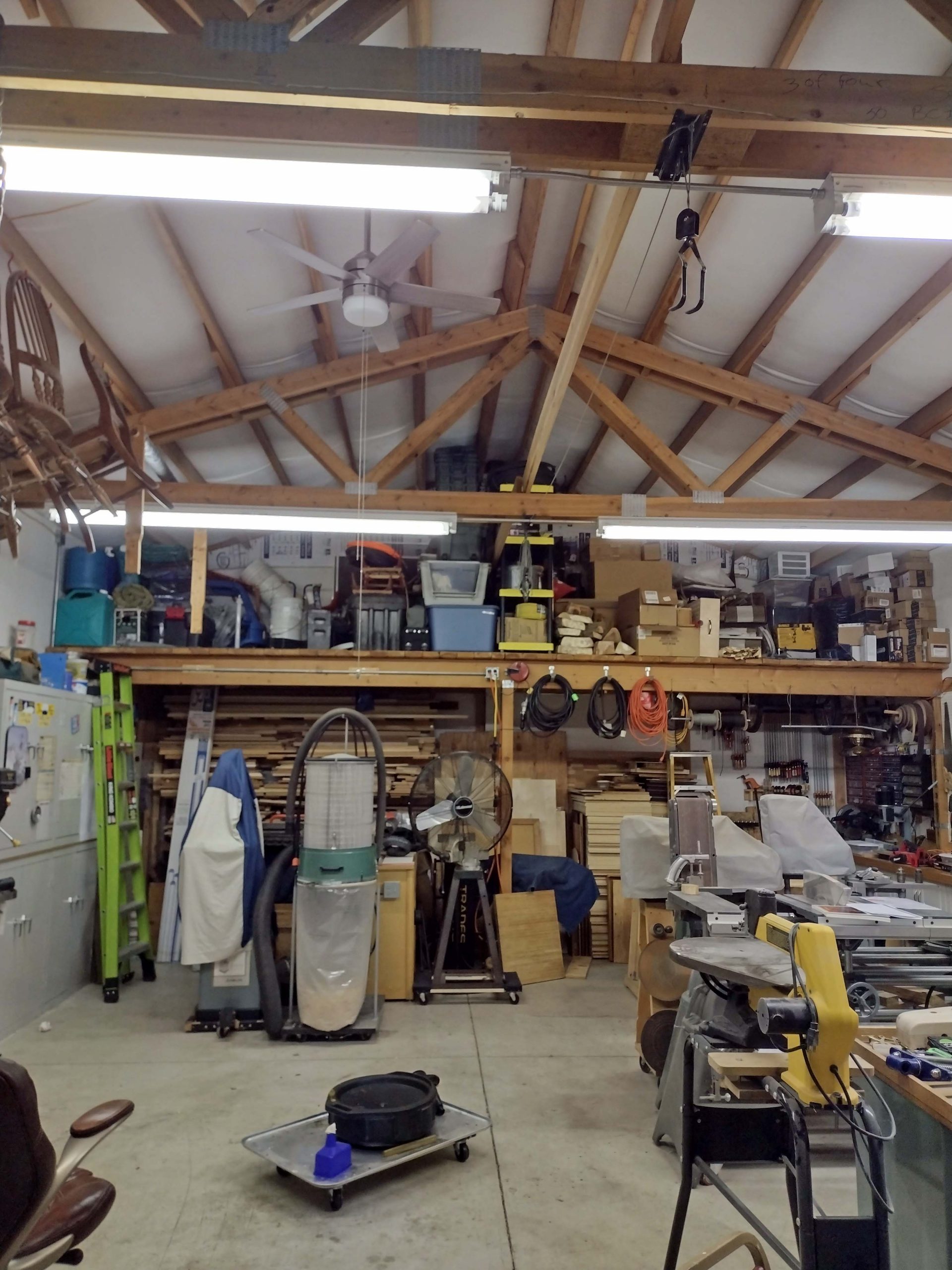
I also installed a ceiling fan to help move the rising hot air down to the lower levels of the shop. The shop walls are 12 feet high, and the center peak is at 16 feet. Hot air rises and it gets pretty hot up there even when it is still cold on the floor. The fan runs backwards to pull colder air up and displace the hot air at the top. So far, it is helping distribute the hot air very well.
Ceiling fan
I also have a Jet air filter on the wall that moves a lot of air, so it also helps move the hot air. It is an energy hog compared to the ceiling fan, though.
Jet air filter
Additionally, I have a “milkhouse heater” that plugs into a 110 V AC outlet. It is a 1500-watt heater. This little milkhouse heater sits on my workbench and blows directly on my hands as I use the scroll saw. It helps a lot. I have used this heater for years in addition to the wood stove, at least until the shop warms up enough.
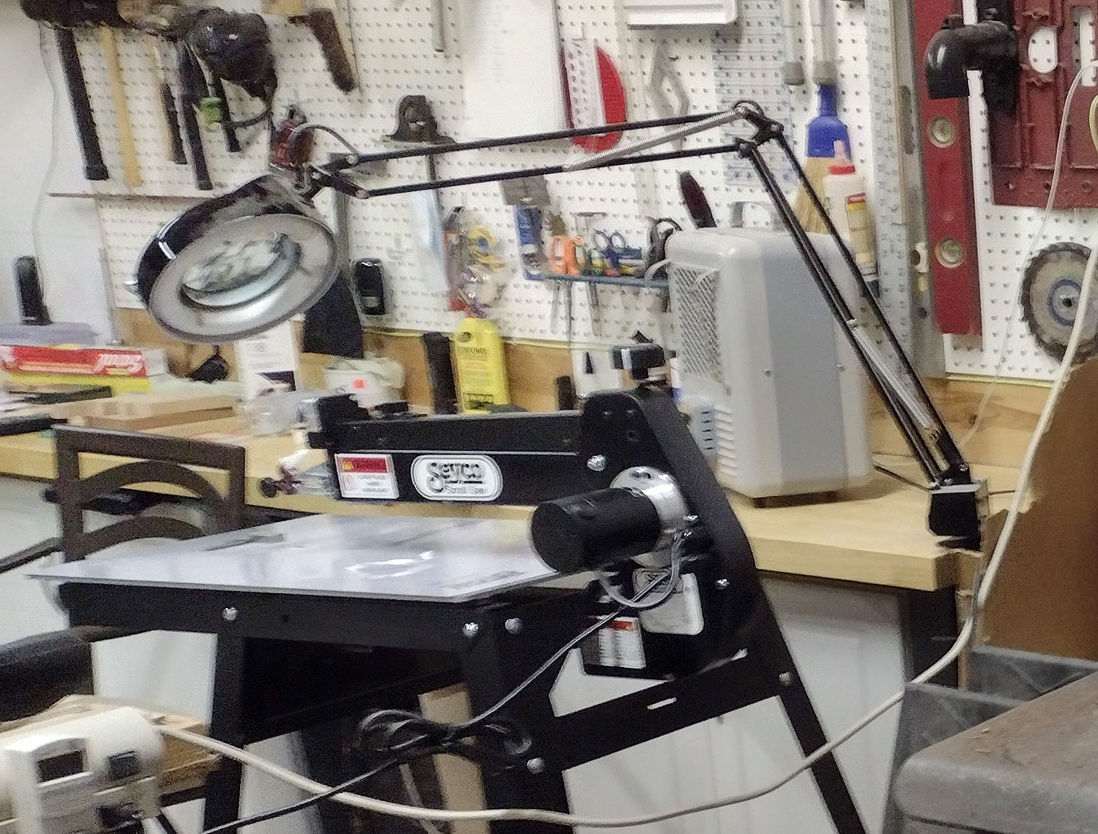
Milk house heater on bench by scroll saw
If I am restricted from burning wood, I have roughly 9000 watts of electric heat I can call on in my sort of insulated shop. That does not sound like much, does it? Just for comparison, the electric central heater in my well insulated house puts out 17,500 watts of electric heat.
Let’s convert the shop heaters to BTU’s. To do that, we multiply by 3.4. So, 9000 watts for an hour (9 kWh) is equivalent to roughly 30,600 BTU’s.
Monetarily, 1 kWh of electricity is costing .14448. If I run my electric heaters for 10 hours for a day, it is costing me (9) x (10) x .14448, which is $13.00.
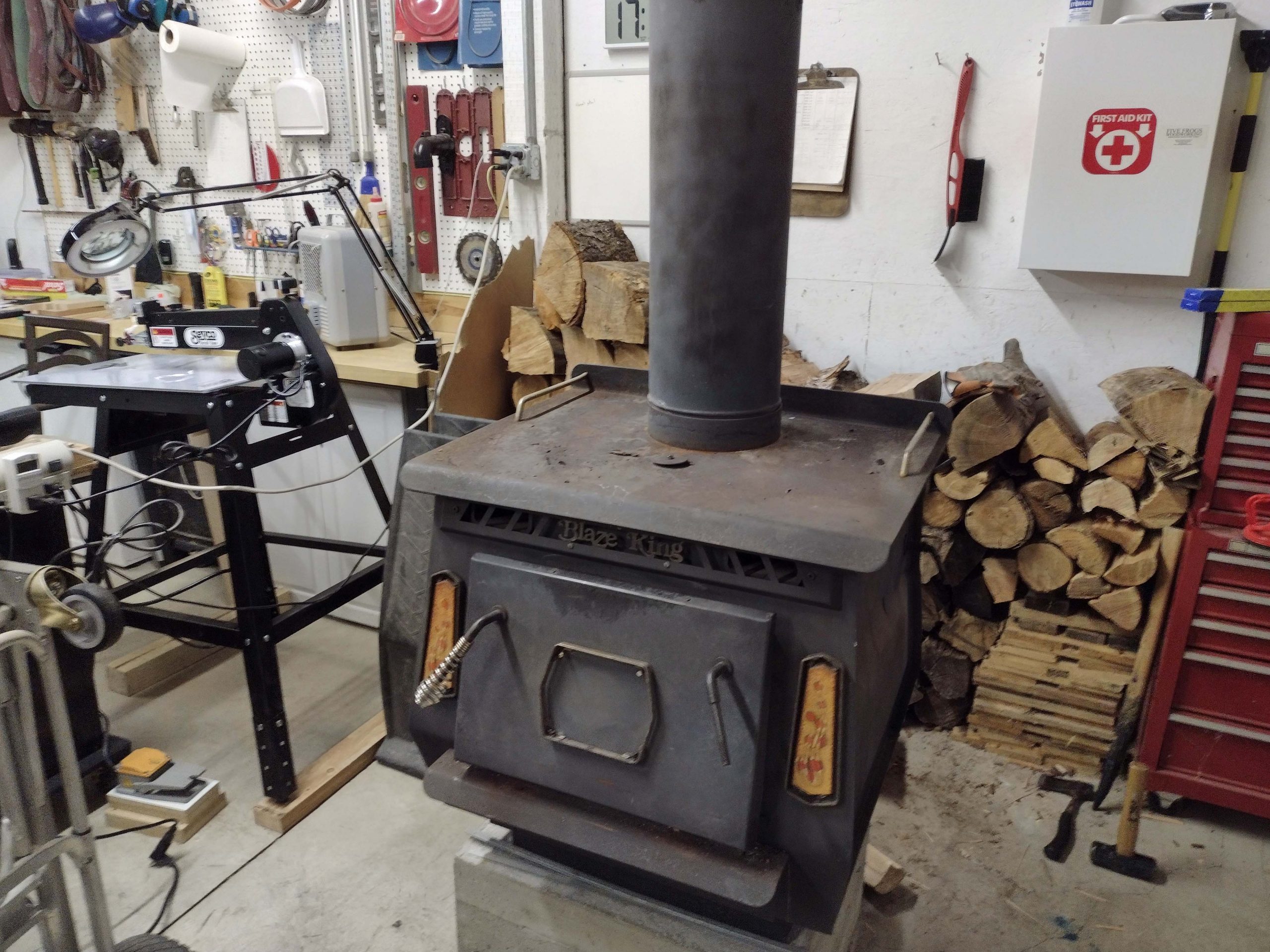
Now, let’s look at wood heat. When the stove is burning, I typically throw in two pieces of firewood every couple of hours. If that is a cubic foot of wood, I am burning .5 cubic feet per hour. Notice that I have my scroll saw fairly close to the wood stove.
Medium sized wood stove
1 cord of firewood is 4 feet x 4 feet x 8 feet, or 128 cubic feet. My last load of delivered firewood was $300 for western larch, colloquially known as “tamarack” even though it is not true tamarack.
So, $300 divided by 128 cubic feet gives $2.34 per cubic foot. For the same 10 hours as above, it is costing $11.71 to heat the shop. Pretty much the same cost, right?!?
Well, wait a minute. How much heat is in that firewood? Most of the common cheap pines, spruce, fir, cottonwood, alder, etc., have about 15,000,000 to 18,000,000 BTUs per cord. The western larch sells for a premium price because it has 23,000,000 BTUs per cord. Depending on your source, these numbers jump around quite a bit. A good hardwood is even better, but hard to get in this part of the country.
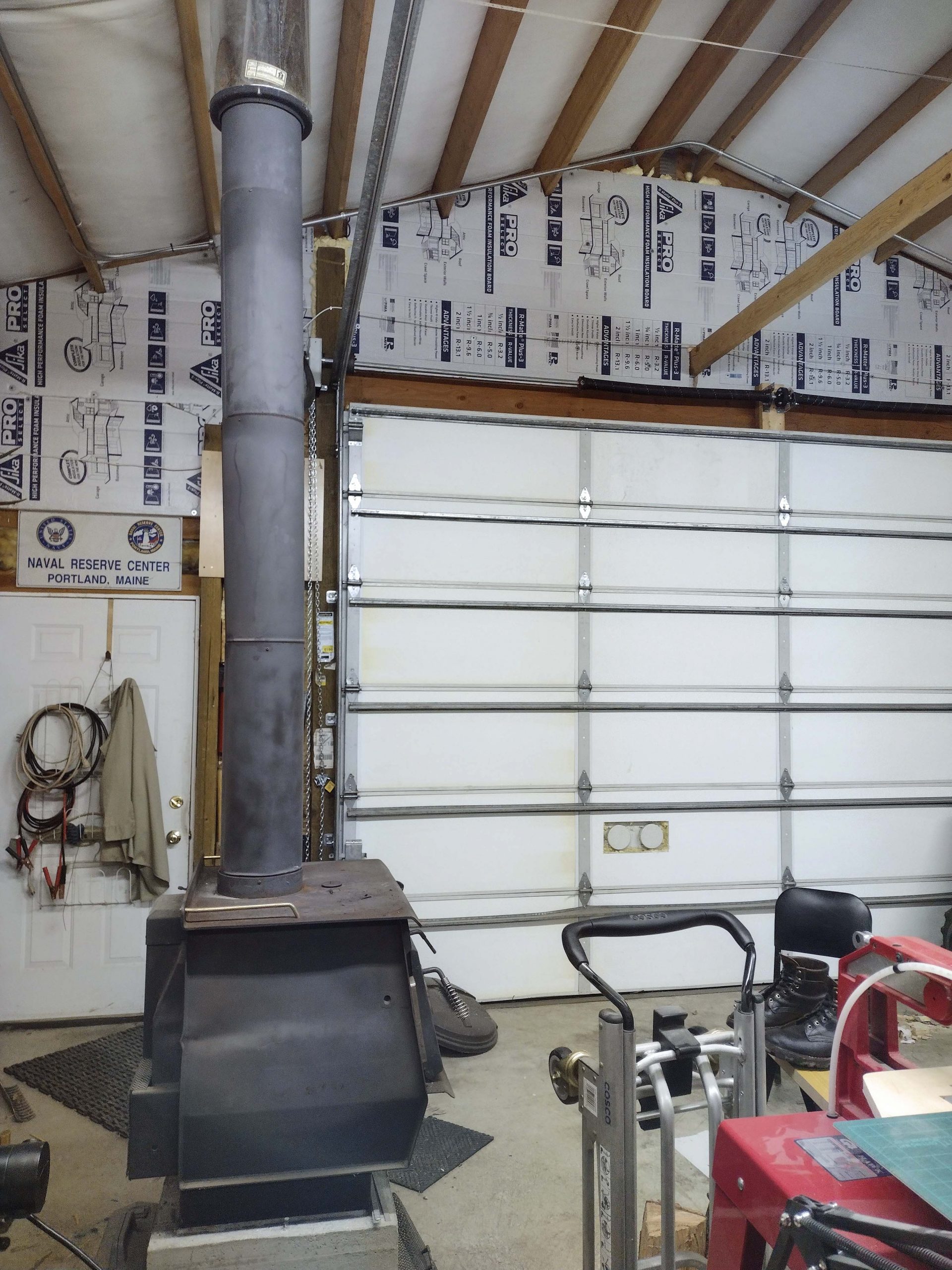
23,000,000 BTUs per cord, divided by 128 cubic feet gives roughly 180,000 BTUs per cubic foot. If I am burning 1/2 cubic foot per hour, that is 90,000 BTUs. It becomes apparent that the electric heat is way more expensive than the wood heat, being almost 4x the cost per BTU. Additionally, the shop is not necessarily well insulated, so the losses can be significant. If it is less than about 20 degrees outside, the wood stove barely heats enough to work. I historically have not tried puzzle cutting if it is that cold outside. The electric heat by itself does not have a chance on a cold day. I have improved insulation in the shop over the last four years. As built, the walls have fiberglass insulation sandwiched between the outside sheet metal and fiberboard on the inside. The ceiling has 2″ thick fiberglass insulation under the sheet metal roof. The peaks were uninsulated as was the roll up door. My kids helped me install foam insulation board on the peaks, and a garage door company insulated the roll up door. But it is still basically just a pole barn at heart.
Door insulation added as well as foam insulation on the peaks.
Going forward, on a really cold day, I will use both heat sources, which will give about 120,000 BTU’s an hour. We are hitting our first cold spell of the season tonight. It has been unseasonably warm so far. We will be in the low teens this weekend. I will be running both forms of heat and see how it works. That will add up to $25 for a ten-hour day. If the puzzle I am cutting takes 10 hours to cut, you can guess that will be factored into the price! However, in my last 100 puzzles, only seventeen of them hit or surpassed the 10-hour mark. Most are under five hours.
Just some “cold” economic facts to consider when pricing puzzles for sale!
Happy Puzzling!
Bob
Posted inTechnical|Comments Off on Heating the shop
In May and June of 2023, I posted a series of blog articles about scroll saws I currently have or have used in the past. I cut some similar puzzles on three of those saws and discussed the different cutting experiences. Of the saws I wrote about, I preferred my Dewalt but indicated I thought the Hawk was a higher quality saw. In December of 2023, my Dewalt started having issues and I needed to replace it. I was in the middle of a custom order and needed something soon. I continued cutting on the customer’s order using the Hawk. When the new saw came in, I finished the order with the new saw.
I decided I wanted to try one of the newer constant tension parallel link scroll saws that have some adjustability of the front to back movement of the blade. (For more on this topic, see my Part 4 entry from June 14, 2023.) There are a number of saw names/brands that fall in this category: Seyco, Pegas, Excalibur, King Industrial, Jet, etc. In sorting through the options, I zeroed in on either the Pegas or the Seyco ST-21. They seem to be functionally identical. I talked to a couple of retailers who were familiar with both. For various reasons, I decided on the Seyco ST-21, although it was pretty much a toss-up.
The Seyco comes with a stand included in the price, the Pegas does not. The Pegas comes with the blade clamps everyone seems to love, the Seyco does not. Seyco has an outstanding customer service reputation. Grobet (Pegas), not so much. One of the vendors that sells Pegas saws in the US has posted on one or more scrolling forums about slow customer service from Grobet. Other forum members have chimed in supporting that customer service with Grobet could be better. The Seyco has a bigger tabletop made from steel. For more $$$, you can buy a bigger table for the Pegas that still is smaller than the Seyco table. When I ordered around Christmas time in 2023, Seyco had a sale in progress that was $100 of store credit towards blades and accessories. Everything leaned Seyco for me, so that is what I ordered.
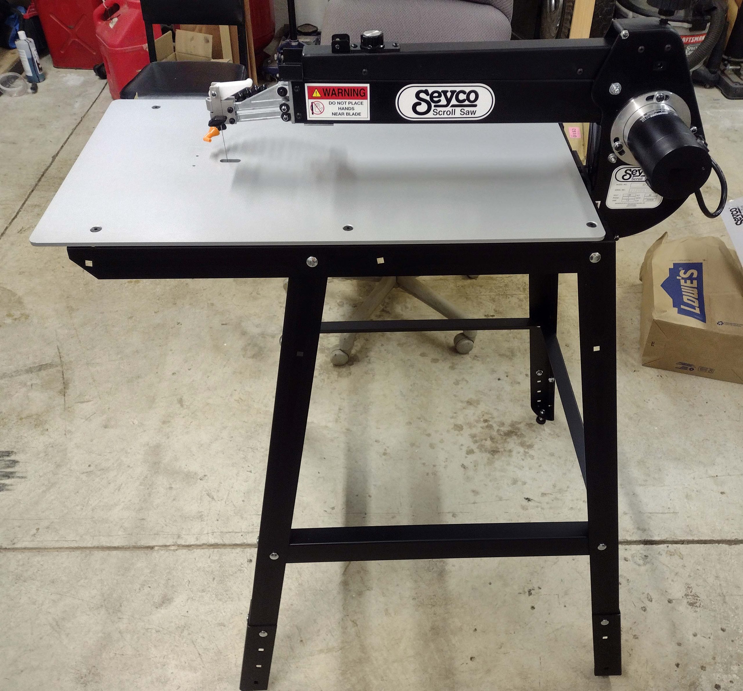
I’ll not bore you with unboxing details, but here is a picture of the assembled saw. Notice that huge rectangular table! 16 1/4″ wide by 28 1/4″ long.
Assembled saw
I will try to follow the same sort of format I previously used. I’ll start with the fact that this is a constant tension parallel link mechanism. Rather than re-explain what that means, I will refer you to my blog entry from 26 May 2023. Scroll saws Part 1 Basic-Info. The advantage to this parallel link mechanism is less vibration than a parallel arm mechanism. The disadvantage is the larger front to back blade motion created by the greater arc of the short arms moving enough to create the up and down blade stroke. This is discussed in Parts 2 through 4.
The advantage to the Seyco style of parallel link saw is that the fore and aft movement can be minimized by adjustments made to the saw. This is the major difference from the Dewalt which led me to spend roughly $400 more for this saw than a new Dewalt would have cost me.
Adjusting the blade movement
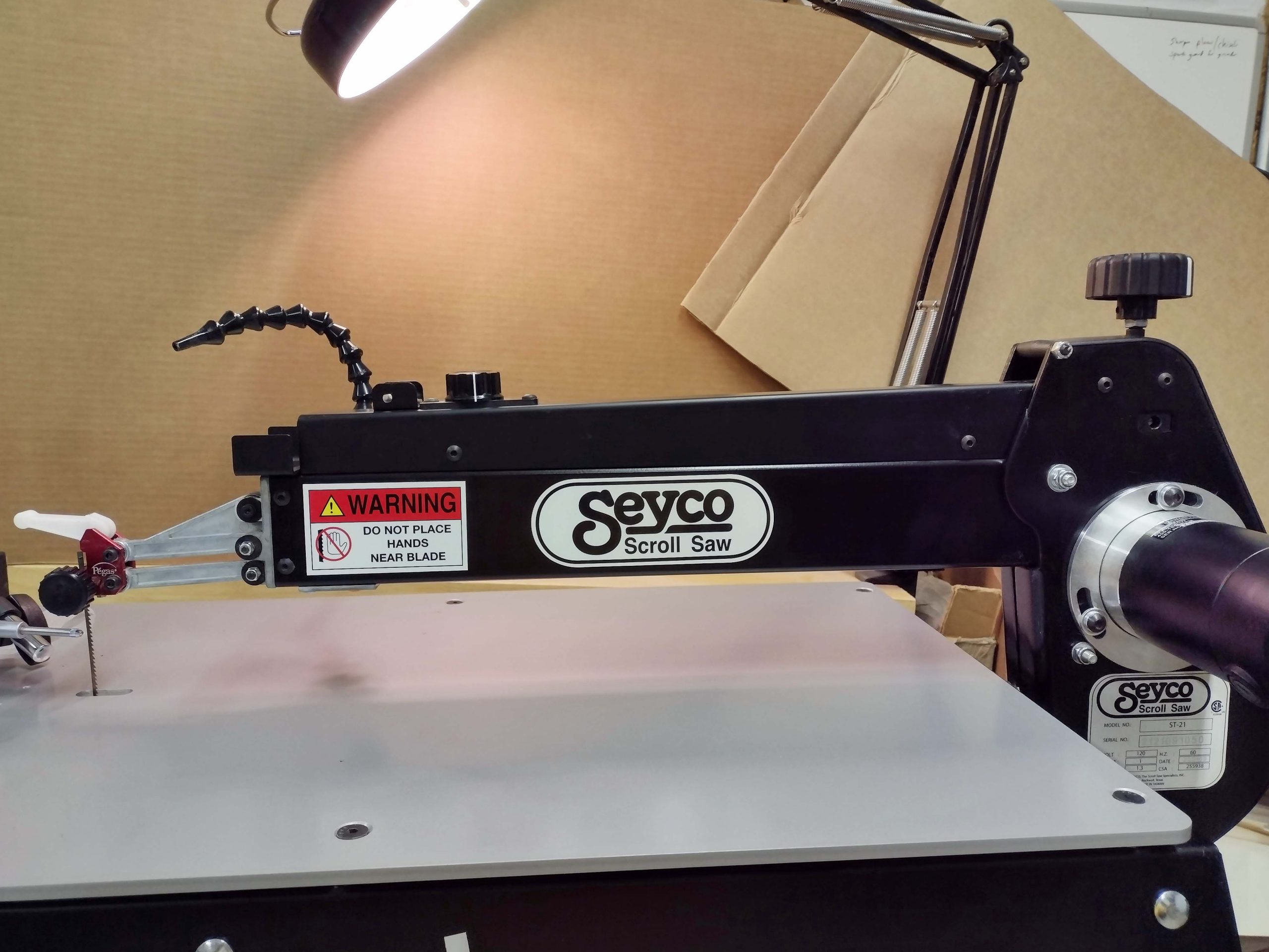
The first step is to ensure the upper support arm is exactly parallel to the table.
Upper support arm
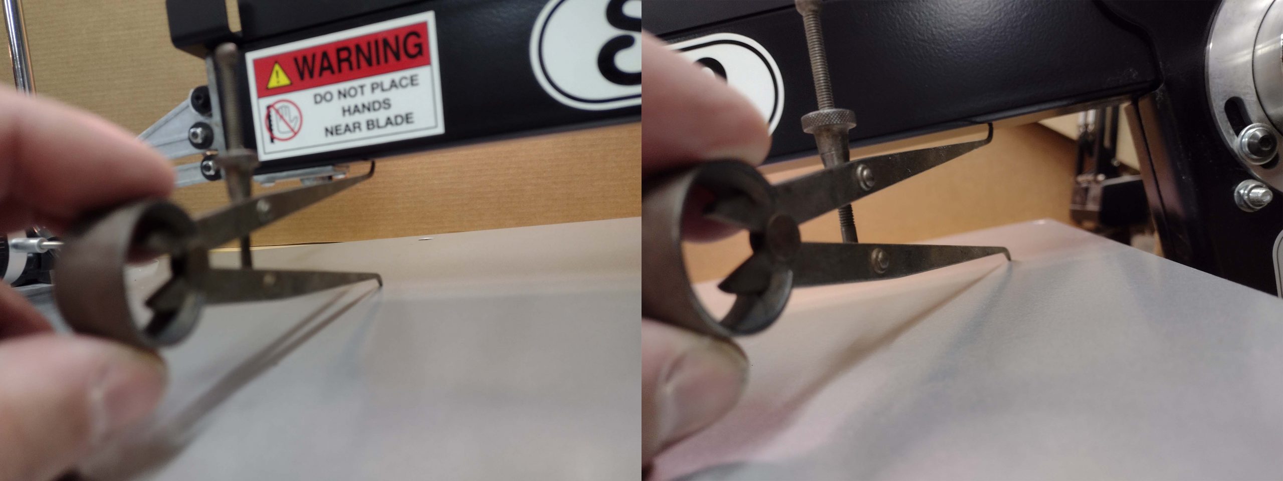
The upper support arm is the large horizontal black metal piece in the above photo. You want the distance from the tabletop to the bottom of the arm to be the same along the entire length of the support arm. This is adjusted (with the blade removed) by twisting the knob on the upper right. You can use a ruler or tape measure, but I used a set of inside calipers.
Using calipers to ensure the same distance front and back
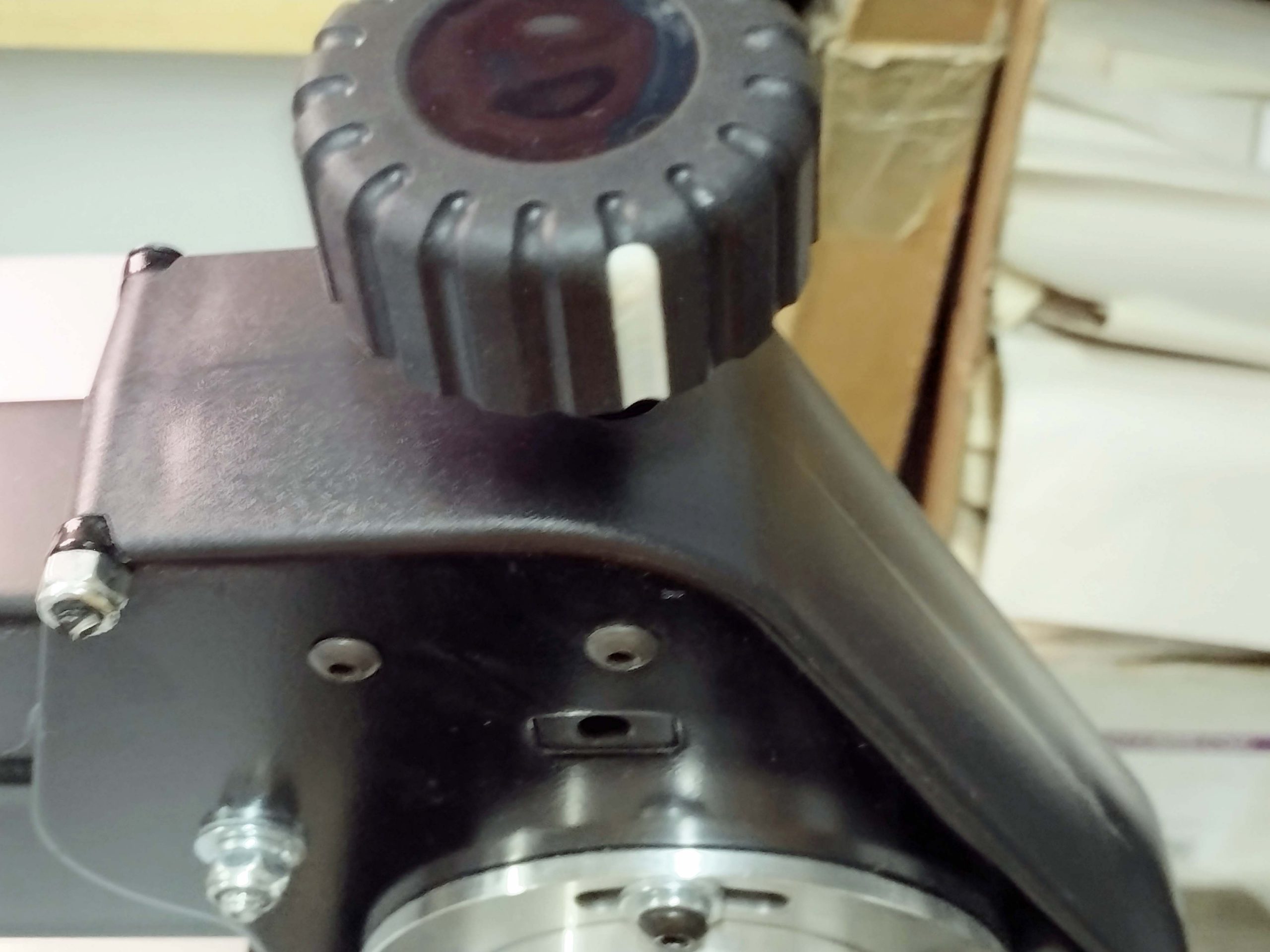
Note the position of the adjustment knob. It has a white mark on it for easy reference. I have not had to adjust mine since I assembled the saw a year ago.
Adjustment knob
Next is to adjust the front to back movement of the blade. Interestingly enough, this is NOT explained in the manual that comes with the saw. So, perform this adjustment at your own risk. The geometry of this saw is identical to the Dewalt, i.e. the arm length is 3 7/8″ and the stroke length is 3/4″. This gives a theoretical range of motion front to back of .018″ to .073″. You may remember that on my Dewalt, the measured blade movement is .036″. On the Hawk saw (different saw mechanism), it is only .009″!
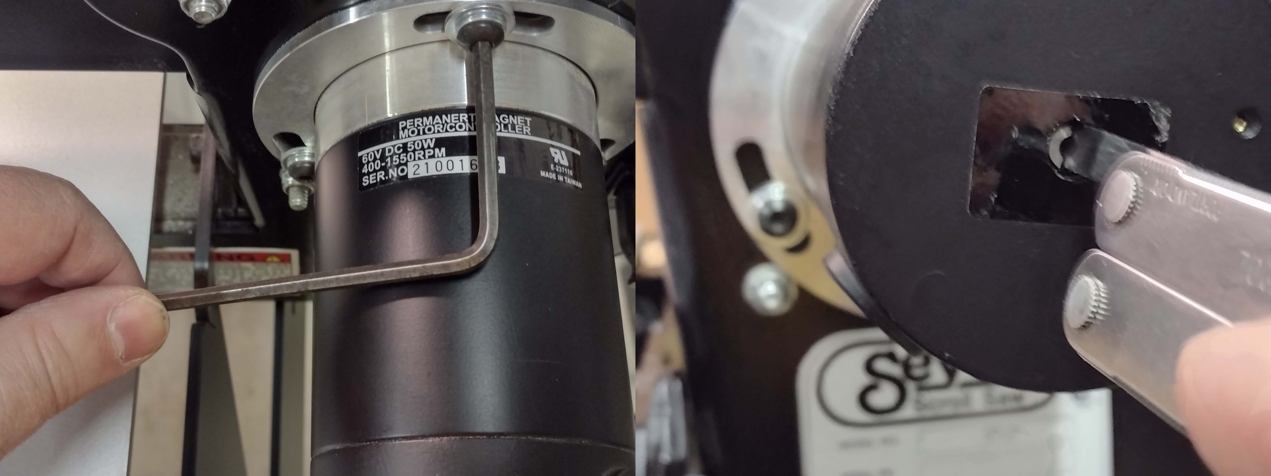
I started by measuring what this came to me with from the factory. To make a firm measuring surface that would not flex, I used a large handheld coping saw blade of rather large size and placed it in the blade holders backwards. Next, I mounted my magnetic gauge to the table with the feeler against the blade. I removed the cover over the motor screw so I could turn the motor with a screwdriver. I then rotated the motor and marked the measurements through the full range of motion.
Initial movement amount as this saw came from Seyco.
It was initially .031″. Not much better than the Dewalt. I loosened the motor mount bolts and twisted the motor through various locations until I had the least amount of motion.
Loosening motor mount screws and turning motor shaft slowly by hand
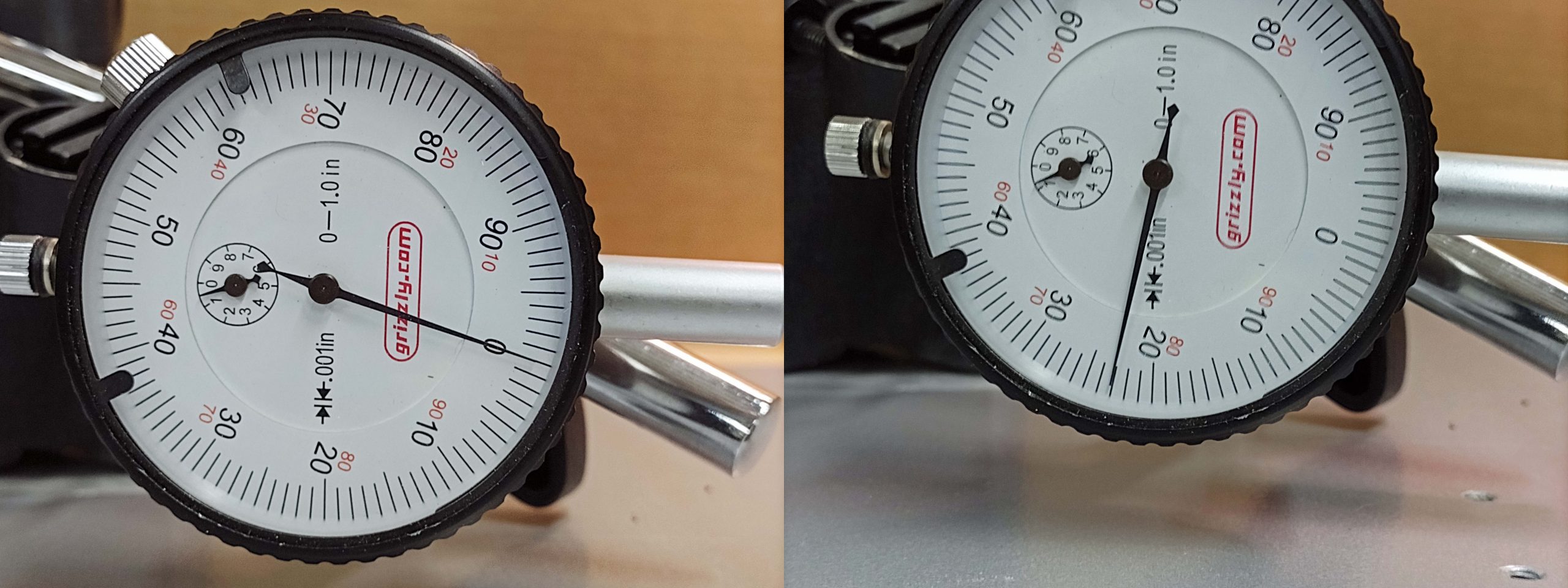
I did not try to find the worst amount of movement, but I had one measurement that went to .045″. The best I could obtain was .023″, which is where I retightened the mounting bolts.
Best measurement achieved of .023″
Geometry tells us the best that could be theoretically achieved is .018″, so this .023″ is fairly close. I was really hoping for the .018″. Anyway, it is better than the Dewalt, but still a long way from the Hawk measurement of only .009″.
Other saw features
Tilt Mechanism
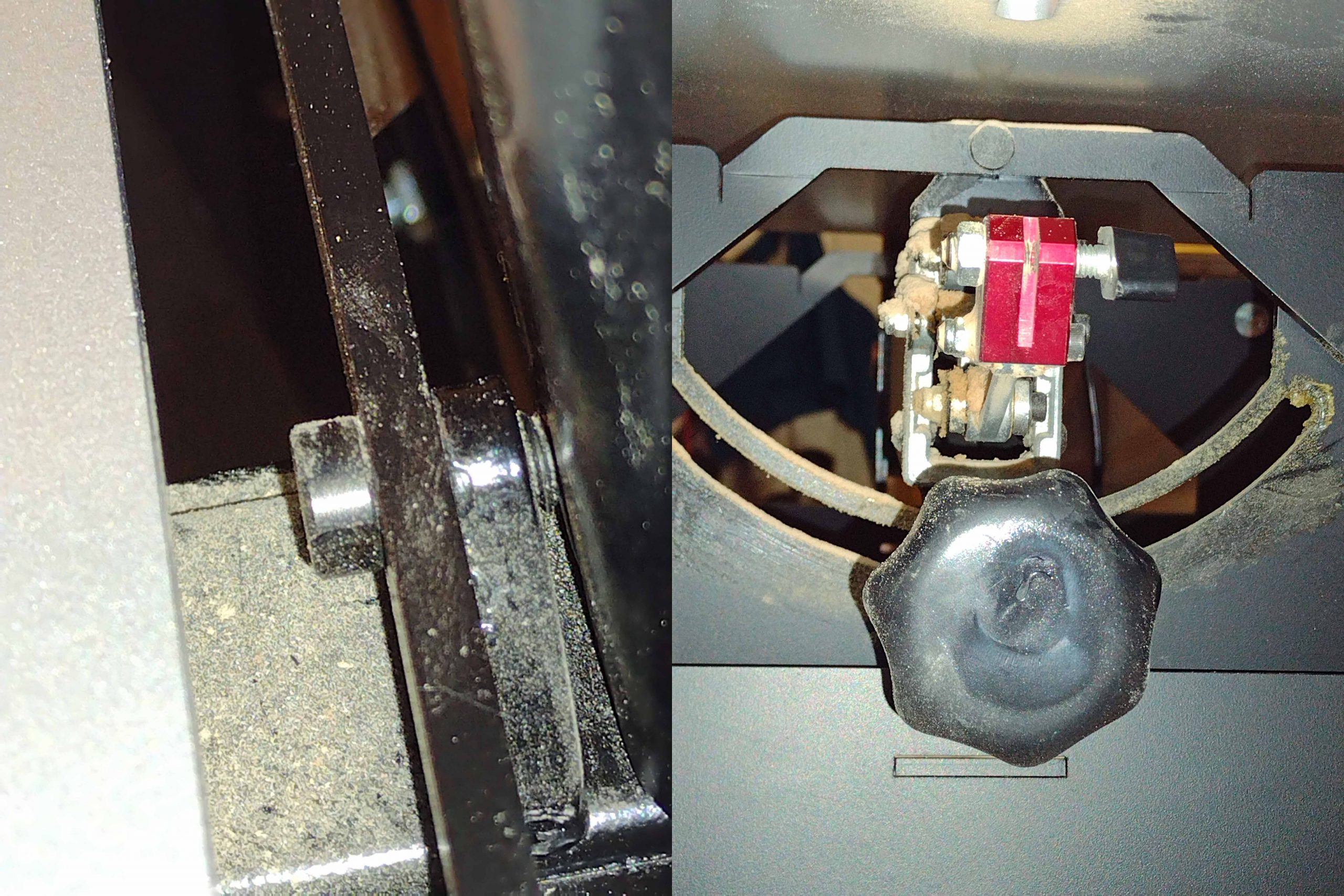
Moving on to the rest of the saw, I’ll start with the tilt mechanism. Unlike my other saws, this saw has a tilting head and blade rather than a tilting table. I absolutely love this feature. That table is incredibly stout and will not be inadvertently knocked out of square with the blade. I rarely cut an angled piece these days, so the tilting method is not critical to me. I do sometimes knock the table on the Dewalt, and it moves. If I am not aware it moved, I can start cutting on the saw without realizing the blade is no longer square to the table.
The saw motor/head assembly is supported by two large pins which go through corresponding holes on the stand. It pivots freely on those two pins until it is locked down by the knob in front under the table. Unlike many of the other saws of this style, there is no gear mechanism employed to tilt the saw head. Nor is there a potentially inaccurate angle gauge to bend down and look at under the table. (I never trust those to be accurate on any of my equipment.)
Rear pin on left, front pin and locking knob on right
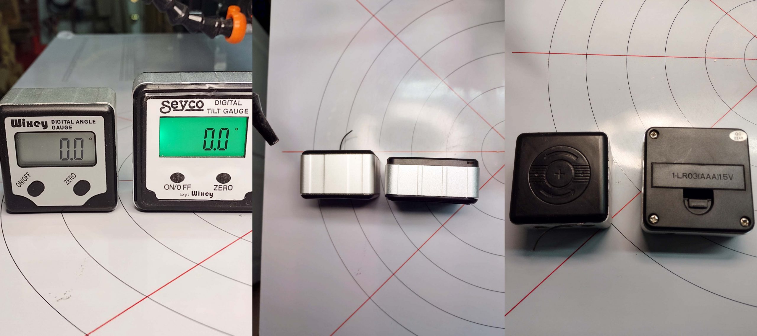
Instead, this saw comes with a digital angle gauge that sits up front where it is easy to see without getting on your knees to look underneath the saw table. This gauge is made by Wixey. It is held in place with magnets on steel components. I had another Wixey angle gauge for over 10 years that I use for table saw set ups, jointer fence alignment, etc. They are pretty good little tools. Here are some pictures of the two of them side by side.
Two different Wixey digital angle gauges
The one that came with the Seyco saw uses inexpensive and easy to obtain AAA batteries. The older one on the left uses an expensive watch battery. After I set up the saw a year ago, I pulled the battery out and put the new gauge and battery in a drawer for storage. I was hoping to use the Seyco gauge for all my needs going forward because of the better battery situation. I pulled it out to take some pictures for this blog post and cut some 7-degree tapers for an inlay project, and after a couple of minutes, it stopped working even with a new battery. I have emailed Seyco about it since it is basically new and unused. I have had this saw for a year now, so we’ll see what response I get. The saw itself comes with a 2-year warrantee, but I do not know if that applies to the angle gauge it comes with. (Edit – I received a response from Seyco. They will indeed replace the faulty digital angle gauge. Hard to beat that kind of customer service!)
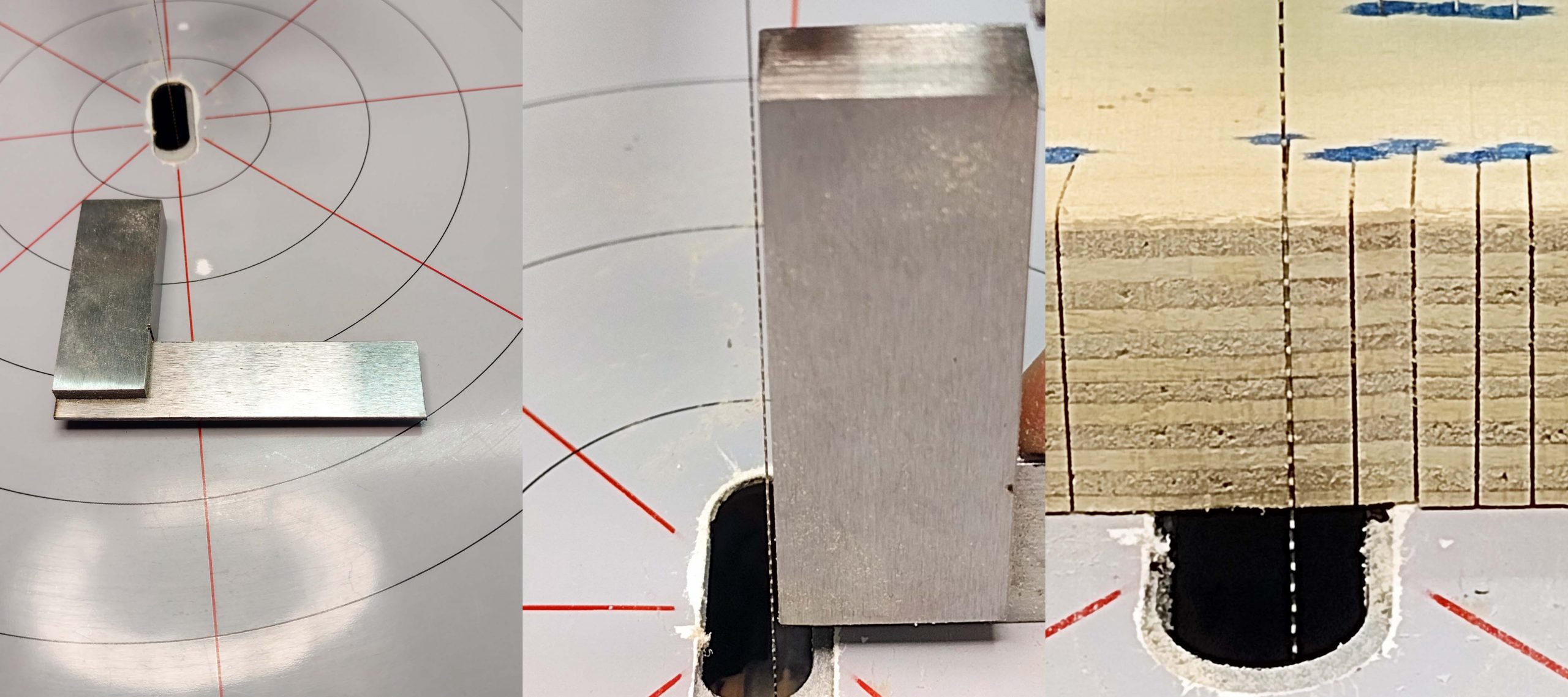
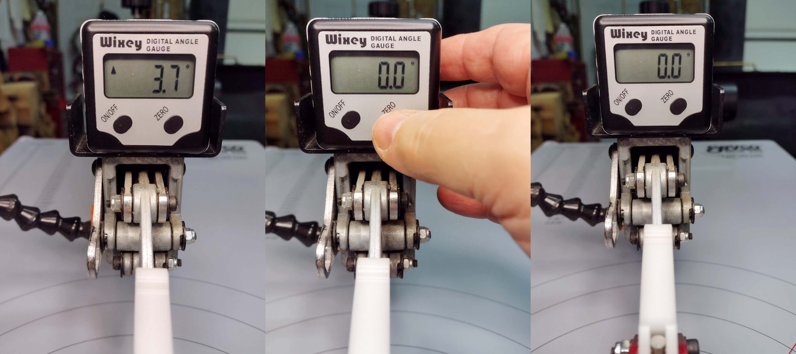
First, you square the blade to the table. The saw comes with a little 2″ engineer’s square for this purpose. I do not normally use a square for this. I just use a piece of wood, cut a slot, and reverse the wood to see if the blade fits in the slot.
Squaring the blade to the table.
Once the blade is square, you zero the Wixey gauge. I had to put a new battery in my old one for this series of photos. When I mounted it and turned it on, you can see it was not zeroed yet.
Zeroing the digital angle gauge
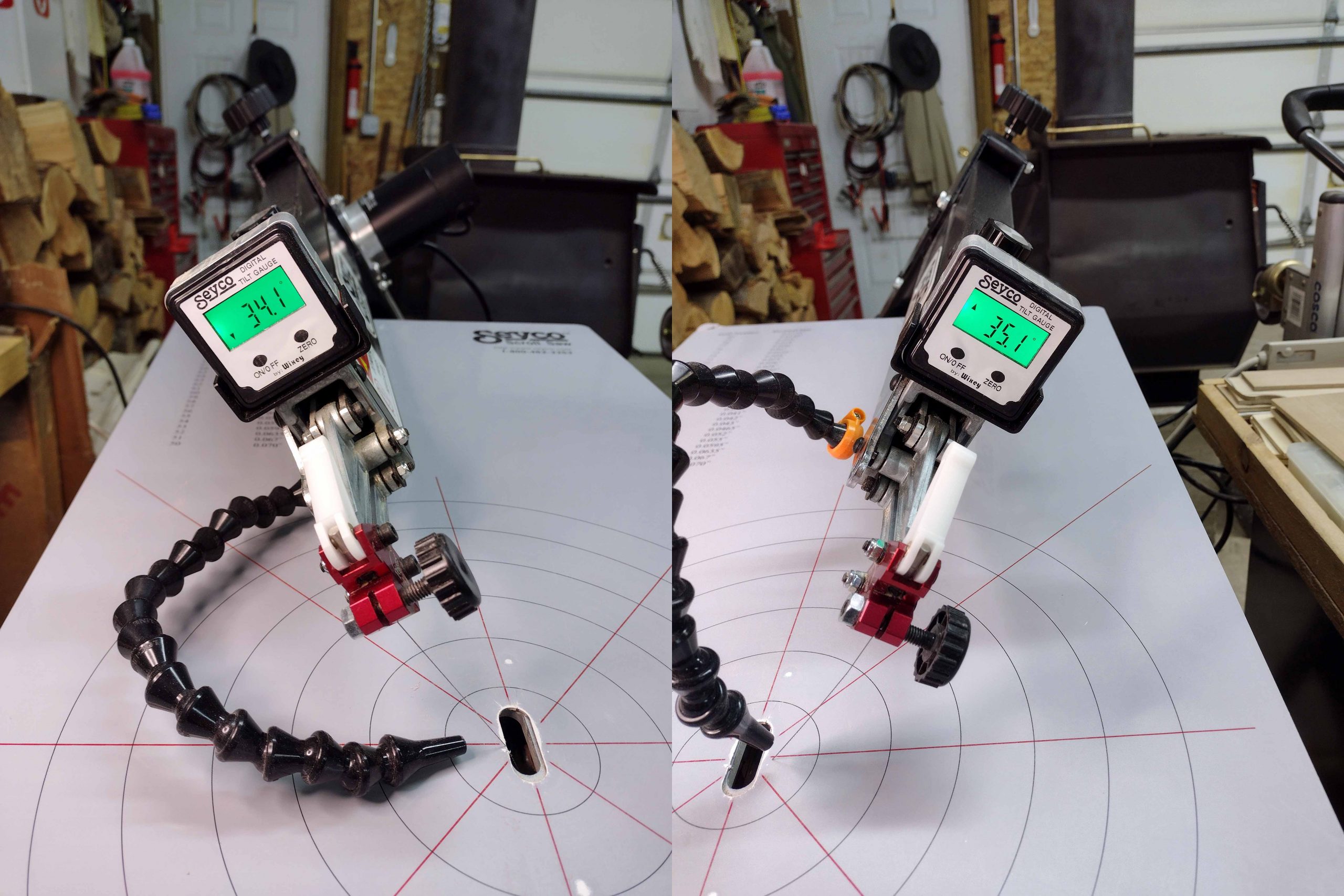
Once the gauge is zeroed, you can loosen the adjustment knob and pivot the saw head to the angle you want. My most common use in the past was at 7 degrees for making some inlay projects. The next picture shows the amount of tilt possible from left to right. This was before the provided gauge stopped working. One item to note is that the saw motor is mounted on the right side of the saw head. When you loosen that adjustment knob, the weight of that motor wants to go full tilt to the right. Be prepared!
Left and right range of tilt motion.
Magnetic table cover
An optional feature I chose was a magnetic table cover with concentric rings and lines. You can see it in the above photos. If you watch Steve Good’s 7-year-old video on this saw, they originally came with the magnetic cover. Now, they are an optional accessory. Not strictly necessary, but I do like the lines converging on where the blade passes through the table. When I am cutting some gnarly twists on the saw, they help me realize I may be pushing sideways too much, which makes a bad cut. After a year, this one is getting wear marks on it. I am not sure if I will replace it when it is time.
Heavy duty stand
The stand is strong thick steel and is incredibly sturdy. As mentioned above, the saw comes with the stand for no additional charge. Additionally, it can be set up as a floor stand as I did, or it can be set up as a benchtop saw.
Here is a picture of the saw stand as compared to the less sturdy Dewalt stand.
Seyco stand vs. Dewalt stand
If you look at the bottom of the legs, you can see there is a short section on all four legs. If you want a benchtop saw, you just use these short pieces without the long sections. Also, you have some adjustability on how tall the floor stand is by attaching the short sections through different holes. Also, you can make the front legs shorter than the back legs if you like the saw to tilt towards you. I often sit in a bar height chair while cutting, so I went for the full height. I just put a board under the back legs if I want it tilted.
Big table
This has a huge table on it. I like the big table that helps support large puzzles when I first start cutting them. Here is the table as compared to the Dewalt.
Seyco vs Dewalt table
Once again, if you look at Steve Good’s video on the Seyco saws, his originally came with a slightly smaller table that had “saw dust collection trays” around it. Those are gone, which I think is probably a good thing.
The table is made from steel and is about 1/4″ to 3/8″ thick. It is coated with something, maybe powder coated. When waxed, it is pretty slick, but I do have that magnetic cover on it.
On/off switch
The on/off switch is pretty small. It is also “protected” on the sides by metal tabs that stick up. I had never used a foot switch before, but it was readily apparent that I would need one with this saw. I did purchase one separately. 25+ years of habits are hard to overcome, but I have adjusted to using a foot switch. I have now purchased another one to use with the Hawk saw and probably will get a third one to use on the Dewalt when I get around to fixing it. If you are not using a foot switch, do yourself a favor and get one.
On/off switch and foot switch
Blade clamps/tension adjustment
This is the one area where I believe the Dewalt is a better saw, including the Hawk saw. The blade changes are quick and easy. On the Dewalt, tensioning is done with a little lever right there with the rest of the controls. I can easily change out a dull blade and continue cutting within 10 seconds without any issues. That includes the time spent pulling a new blade out of the container I store them in.
On these newer saws, there really is not a tension adjustment. You replace the blade and move the tension release lever, and the blade clamps automatically adjust using a spring built into the upper clamp. I at first broke about a third of the new blades I installed in the saw before even turning it on. At first, I thought it was a defect in the factory blade clamps, so I bought the Pegas replacement clamps that people rave about. No difference. I have to install the blade with a little curve in it to keep the tension from exceeding the blades strength.
It turns out that it is really an issue with the blades I like to use, not the saw’s fault. I use the Pegas MGT 2/0R blades. They break easy and this is indeed discussed on a few forums and has been mentioned on a couple of Facebook groups. This really came to life for me while cutting the double-sided pocket watch puzzles last summer for the 2024 Puzzle Parley puzzle exchange. I tested a number of different 2/0 size blades to compare the cut roughness on the double-sided puzzles. None of the other blades broke on me when placed in the saw. Just the Pegas MGT 2/0R blades. This was never an issue with the Dewalt style of blade clamp and pressure mechanism, as the tension is manually adjusted. You just move the tension lever until the tension is correct.
I still prefer to use the Pegas MGT blades, but I have to ensure there is a little bit of curve when I install them in the saw. When I tighten the blade, sometimes I have to release the tension lever and readjust because the blade is too loose. Blade changes just take longer than they do on the DeWalt.
Speaking of reverse tooth blades, you may remember from my prior blog posts that different saws have more or less of the reverse teeth projecting above the table. Like the Dewalt clamps, with these clamps you can position the blade higher or lower with respect to the table. I can position the blade so the reverse teeth only come up about 1/8″. This gives me the cleaner cut on the backside without causing tear out on the front side.
1/8″ of reverse teeth showing above the table
Summary
After a year of using it, I am very happy with the saw. I did not cut another dragon tails puzzle for this, as I still have some unsold dragon tail puzzles for sale. I don’t currently need another one! So, I cannot compare cutting times per piece like I did before.
I love how sturdy it is and the non-movable table. I do not normally cut at an angle, so the tilt mechanism does not matter to me. I would say that I do like the digital angle gauge accurate to 1/10th of a degree that is visible from the topside.
The saw is practically vibration free. I put a glass of water on the table while running it at full speed and barely had any ripples in the glass. I put the same glass of water on the Hawk table, and the saw got wet. Really wet, until the glass fell onto the floor. If it was running, the Dewalt might have had a splash or two with that test.
Besides cutting puzzles, I have used the saw to cut some animal shaped wooden blocks for the grandkids to play with when they are here. With the right blades installed, it plowed through 3/4″ thick maple, hickory, and alder with ease. Very smooth polished edges to the cuts which required no sanding.
Is it better than a Dewalt? For the most part, I would say “Yes, it is better than the Dewalt.” Was it worth $400 more better? I guess that depends. If looking strictly at the front to back blade motion issue (which is why I originally bought it), that little bit of adjustment was not worth the extra $400. Looking at the stand and the sturdy tabletop with some of the other features, I am quite happy I have it. If I did not have the extra money, I would have bought a Dewalt and also been quite happy with it. The Dewalts are great saws and much more affordable. Plenty of people are using Dewalts to make many many jigsaw puzzles. I just would not have had that itch scratched: “are the $1000 saws better than the $600 saw?” I do not regret buying it.
Is it better than a Hawk? $1000 saw vs. a $1600 saw? For what I am primarily using it for, I like the Seyco (and Dewalt) better. The Hawk does cut more precisely. Blade changes are a little more finicky on the Hawk. The speed range on the Hawk does go down to 40 strokes a minute. (Why would I need that? The Hawk, with an optional coolant drip tank, can be used to cut stained glass with diamond blades). The Hawk can adjust the fore and aft angle on the blade for more aggressive cutting. The Hawk can be modified with an optional wide and lower set of legs for use with a wheelchair. Not really a quality issue, but I like that the Hawk is still made in the U.S. I like to support American workers. The Hawk is a higher quality saw overall, but I prefer to use the Seyco or Dewalt for puzzle cutting just because of blade changes.
Of course, all of these can be found used for a lot less money. New ones have a list price that can often be undercut due to sales. I say $600 for the Dewalt as that is the current price I find online, but I have seen it recently for significantly less. You do have to be careful on what it includes (stand or no stand, for example).
And, of course, there are used saws out there. This is the seventh scroll saw I have purchased in my lifetime. It is my first brand new one. I would have bought a used one, but Pegas and Seyco saws do not pop up on craigslist or Facebook Marketplace near me. I think there was one Pegas before Christmas, and the seller wanted almost as much as a new one delivered. Not happening. Currently, there is a Dewalt about 50 miles from here that is listed for $425 that is advertised as “assembled but never used”. It includes a stand, a light, and a bunch of blades.
I hope that this is interesting and useful information for someone. It took me too long to write for it to be a total waste of time! <smile>
Happy Puzzling!
Bob
Posted inTechnical|Comments Off on Scroll Saws (Part 5 – Seyco ST-21)
Over a year ago, I started a project to run comparison tests of various wooden materials available for puzzle creation. Three blog posts resulted: the first talked generalities about plywood types, the second talked about the specific types of plywood I would be testing, and the third presented results from cutting ten of those specific types. The first article explaining plywood types and terminology was posted on November 10, 2023. The third blog entry with the first set of results and observations was posted on December 13th, 2023. Now that it is December 2024, I should probably catch up with the rest of the samples and finish this.
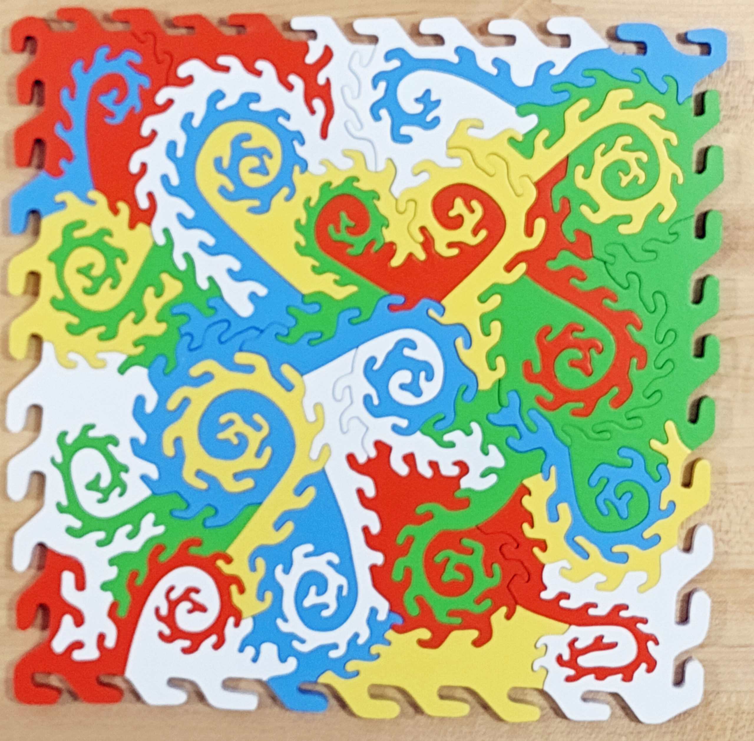
Just as a reminder, I was cutting the same size puzzle with the same size and brand of blades for all of these. I was cutting them with a John Stokes inspired piece style that my wife named “Dragon Tails”. The only difference was to the different types of wood used. I cut these remaining samples primarily in February and March of 2024. However, my Dewalt scroll saw was taken out of service in December 2023 and replaced with a new Seyco saw. That really should not make a difference as far as this comparison goes, but it is a difference.
1/4″ Maple Cabinet Grade Plywood
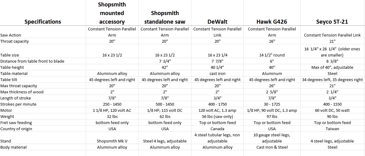
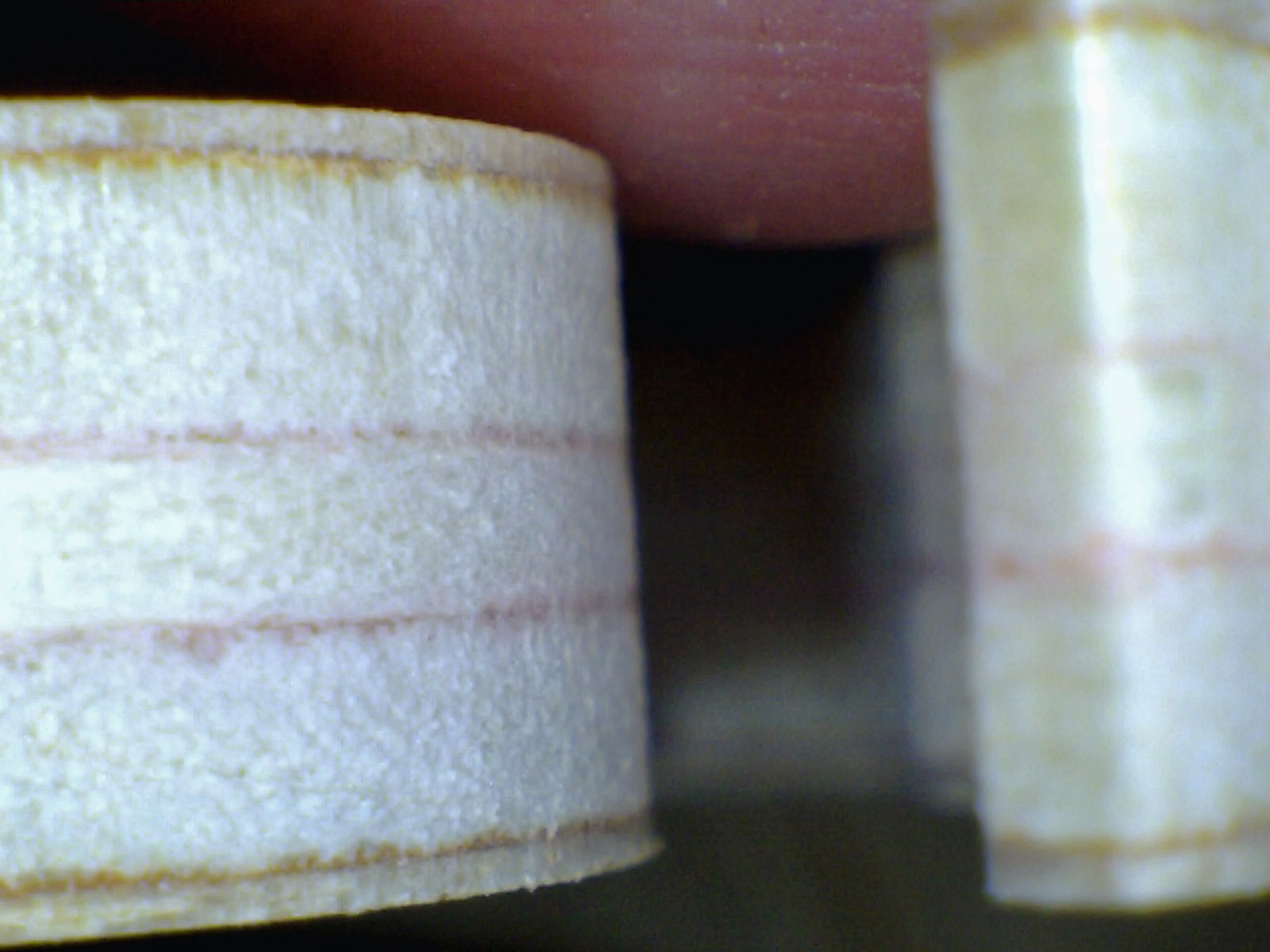
You may remember that cabinet grade plywood is a step up from construction grade plywood. It has more layers or plies made from a higher quality of wood, often a hard wood. At least one outer layer is aesthetically pleasing. It is not necessarily void free, however. Here is a side view of two pieces of different thickness cabinet grade plywood.
Nominal 1/2″ and 1/4″ cabinet grade maple plywood
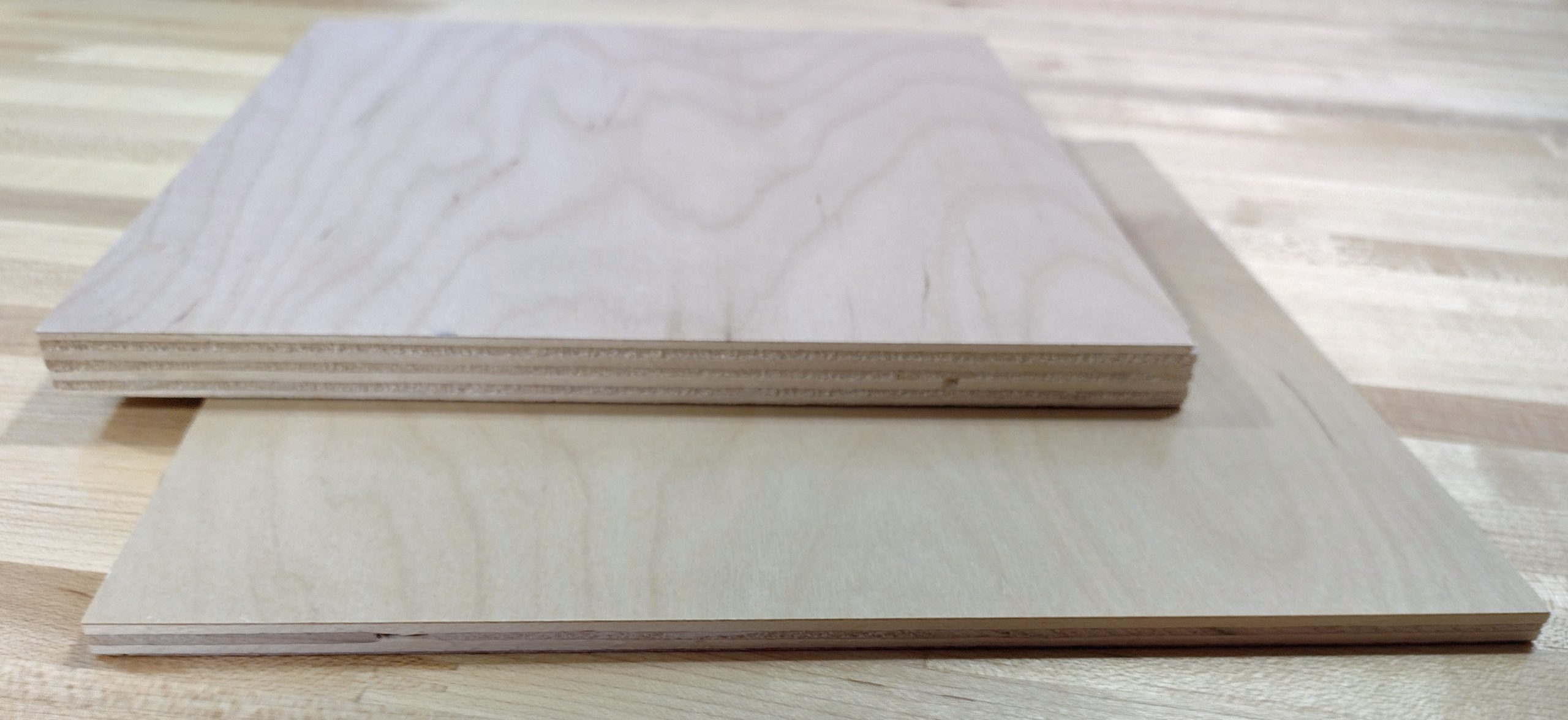
You can see the 1/4″ one above has a void clearly visible in the edge view. This piece of plywood is the test subject here. Because these are cutoffs from a local cabinet shop, the pretty side has a clear finish on it. I cut this with the finish side up. As with the previous puzzles, I started by cutting the decorative edge.
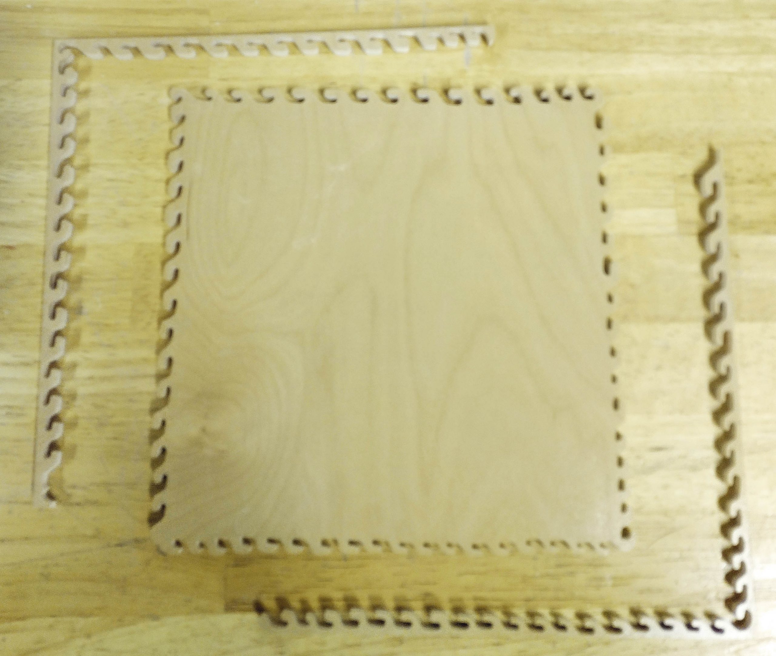
First is to cut the decorative edges
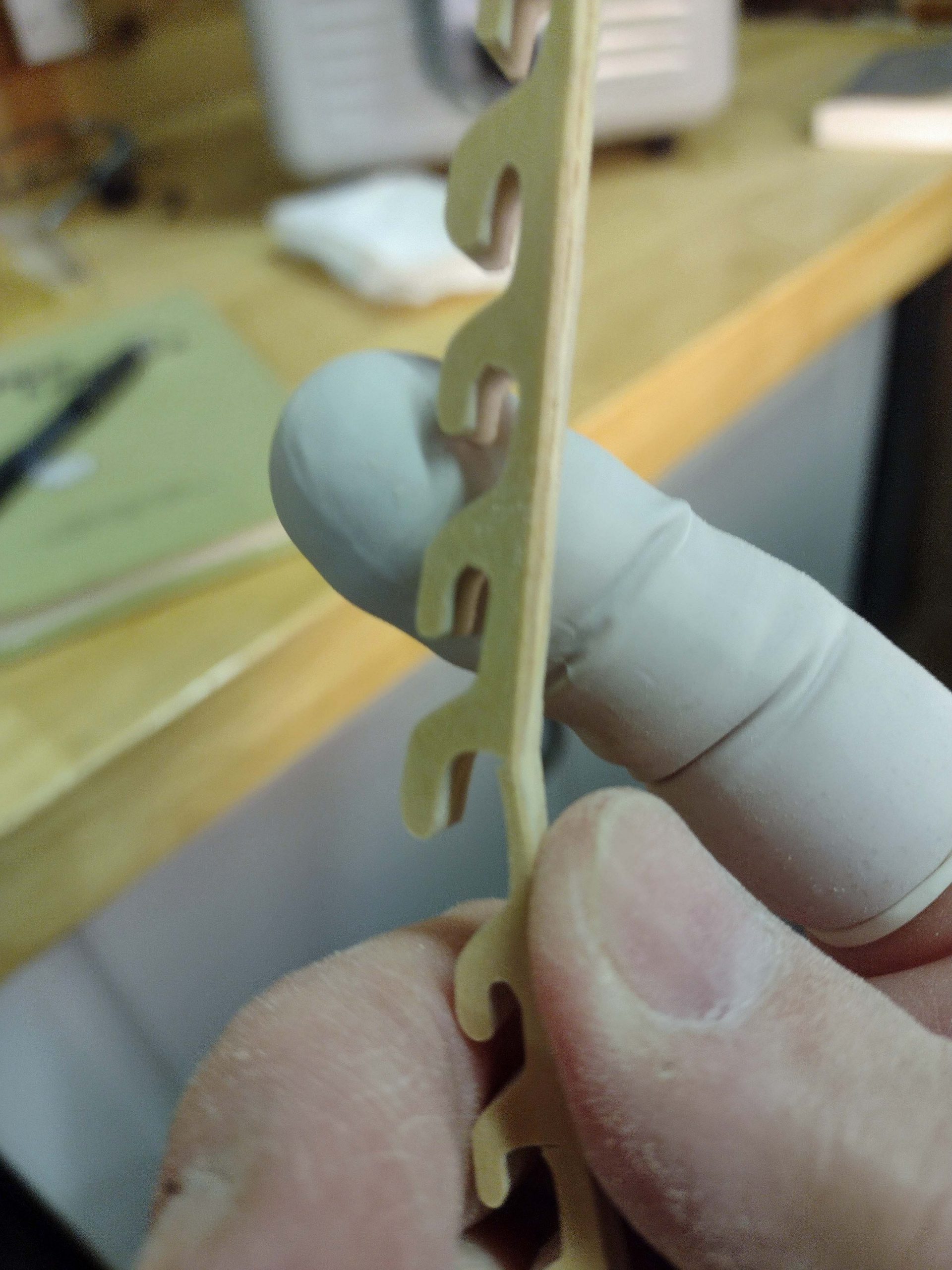
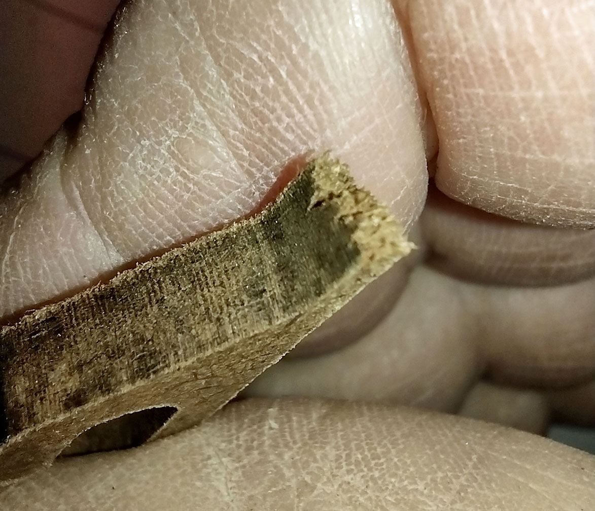
As before, I tested the cut off pieces to see how strong they are. They did not seem to be unusually weak, but definitely not as strong as a multiply such as Baltic Birch or Appleply.
Testing cutoff for strength
This stuff cut relatively easily. Part of it may be because it has less layers of glue, which is hard to cut. The top side with the finish cut beautifully and basically splinter free.
Top side of puzzle – free of splintering
It left a highly polished cut on the internals.
Quality of cut edges
The backside was a different story. Plenty of splinters and even pieces of outer ply coming free.
Missing veneer
Here is a shot of an internal void with other damage.
Internal void
In finishing the puzzle, I was able to repair or minimize all of the issues with the exception of the one in the above picture. For that one, I was able to salvage the missing material and glue it to the piece, but a close examination of the completed puzzle shows the flaw.
Flaw in finished puzzle
Since this piece had a clear hard finish on one side, I made it the back of the puzzle. I painted the unfinished side with acrylic spray paints and made it the front. This is a fun puzzle to assemble. It is easier than one that is painted on both sides, as it is clear which side is up, and which side is down. Here is the painted front of the puzzle. It has been 9 months since I cut and finished this puzzle, but I can quickly observe four flaws in the veneer. Can you? Three of them are on the edge and really do not make a difference. The fourth one is the one pointed out above.
Painted front of puzzle
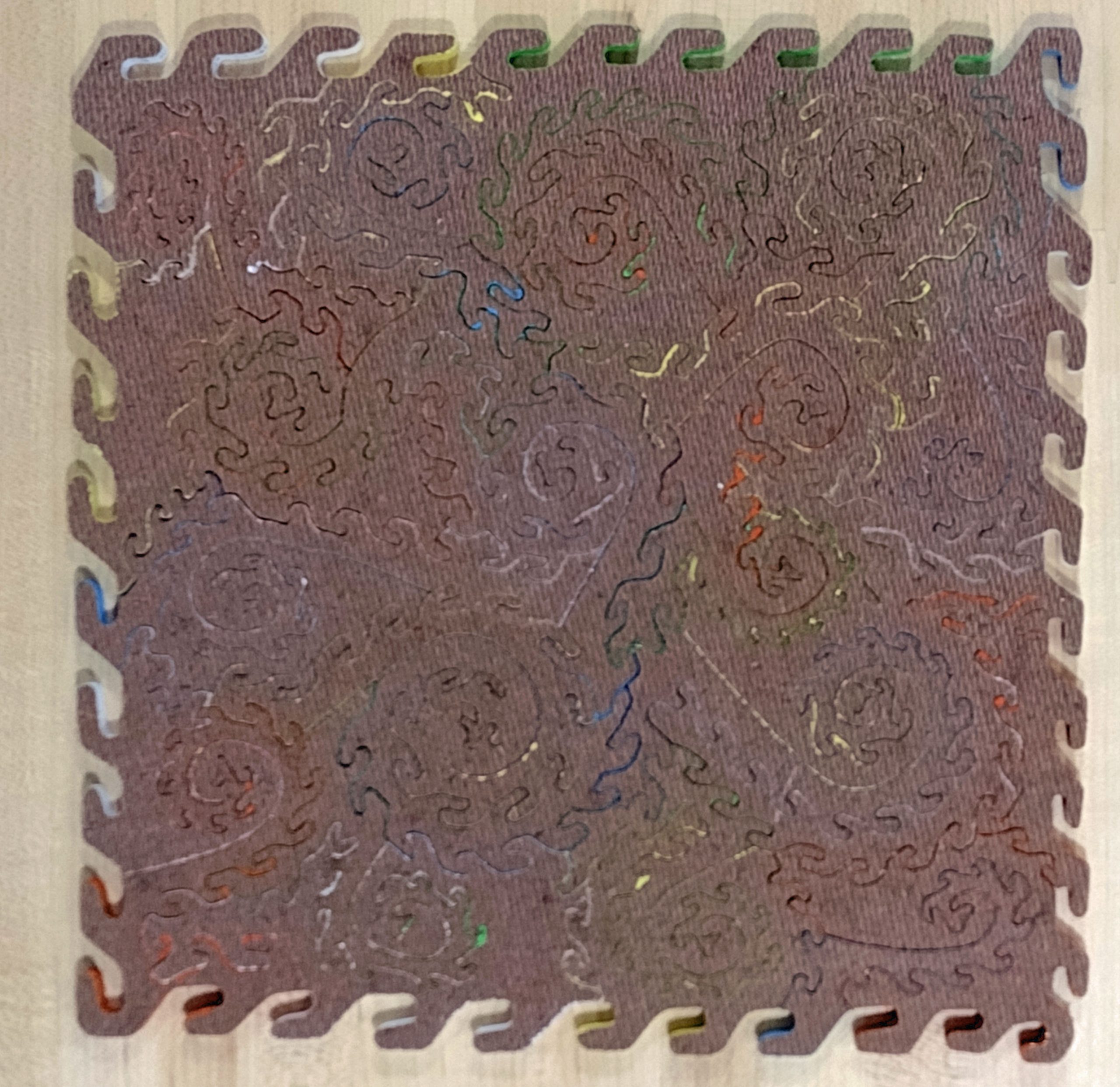
Here is the backside with the clear finish.
Solid maple
Moving on, the next puzzle was cut from solid maple. No plies here!
First was to cut the decorative outside edge.
Edge cut
Next was to test the relative strength of the edges. Since this is not plywood, grain makes a difference. For the part with the grain running longitudinally, this was the strongest wood tested. It held up very well.
Longitudinal grain
For the section with the grain running the other way, however, it was a different story. This is the hazard with narrow pieces of solid wood. It broke very easily. Having said that, after cutting the puzzle I wiggled some of the pieces that looked like they may be vulnerable. Given that the tabs are relatively short, they seem to be fairly strong, and I did not break any of them.
Transverse strength is low
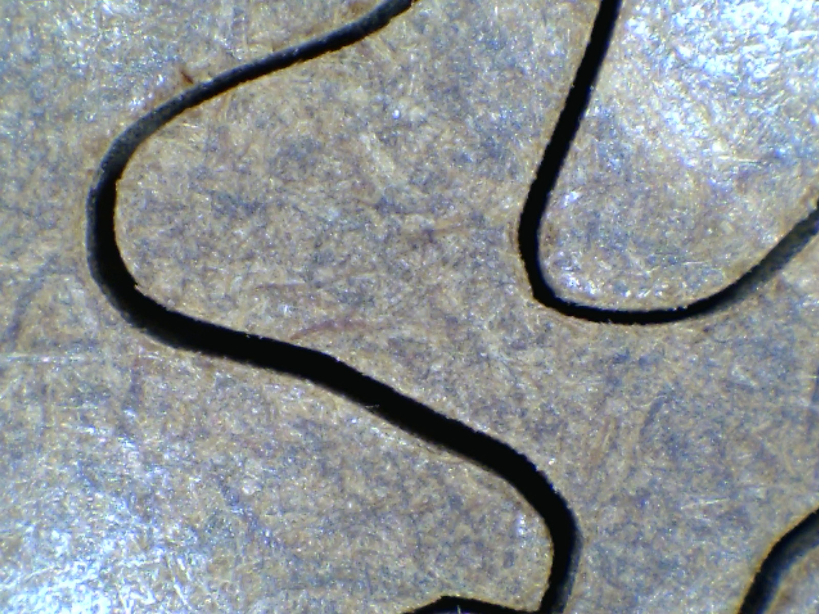
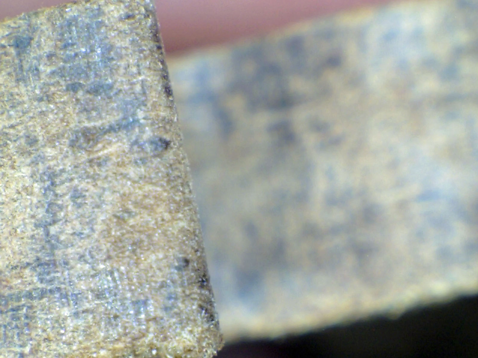
There was really no splintering that occurred while the cutting was going on. That is the advantage of a solid hardwood. Here is a close up with the zOrb magnifier of the front.
Close up of front cut
Here is a shot of the fuzz on the back that is easily removed by light sanding. There is no splintering, just “fuzz” from the saw blade passing through.
Fuzz on the backside
Being solid wood, I opted to finish this front and back with different shades of Danish oil finish.
Front side
And the back.
Backside
1/2″ Maple cabinet grade plywood
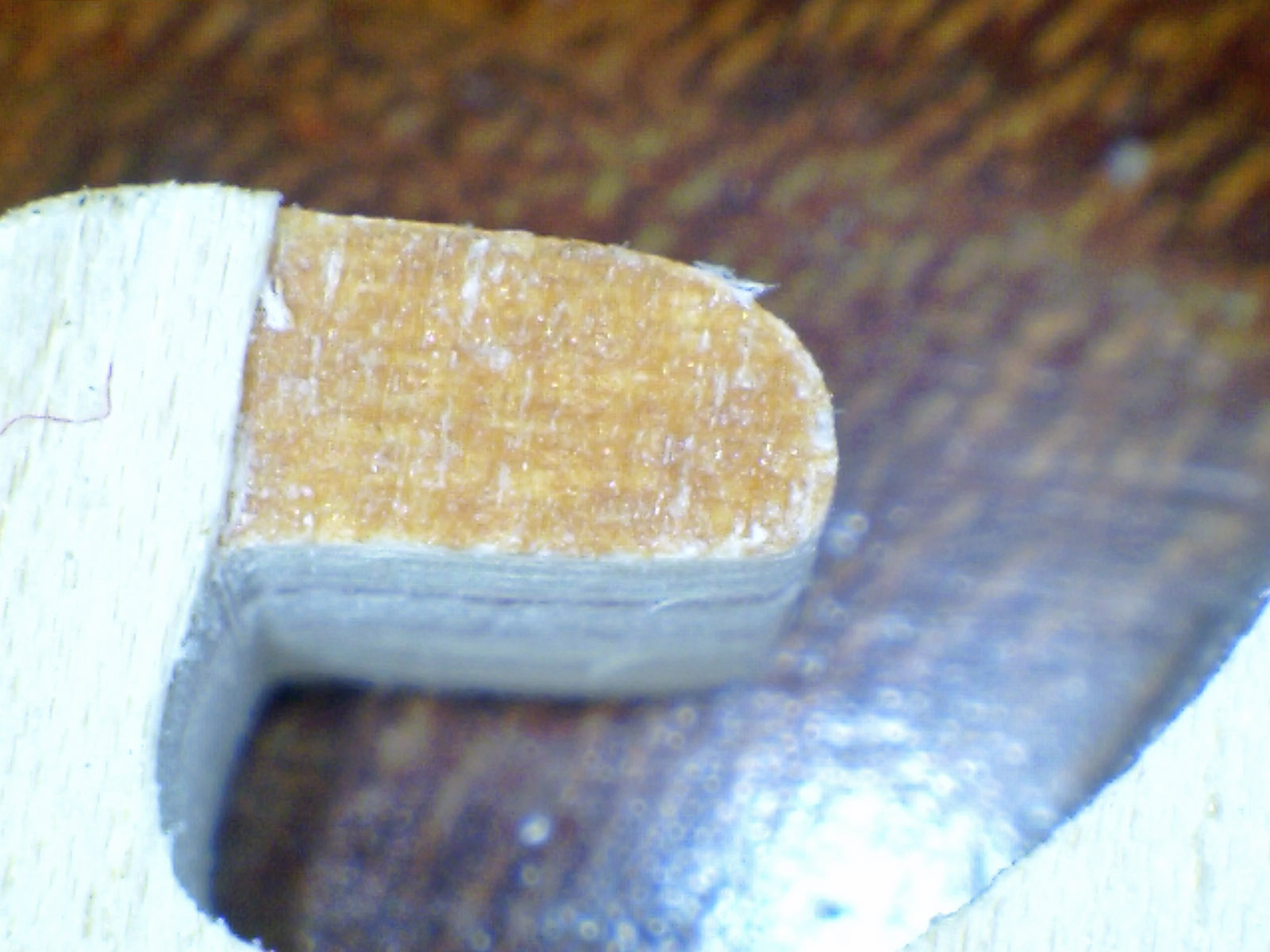
This one is an outlier because it is cut from nominal 1/2″ plywood instead of 1/4″. I reassembled these puzzles to jog my memory as I was writing this blog entry. I have to say this one may be my favorite out of all of them. The 1/2″ thick wood just feels different. It was very satisfying to assemble.
Thick pieces!
As usual with this puzzle piece style, start with cutting the decorative edge and testing the relative strength of the edge off cuts. The strength test was actually meaningless, since the wood is twice as thick. Comparing it to the 1/4″ material is not a fair comparison.
Edge pieces cut
Strength test
As with the 1/4″ thick cabinet grade material, I cut it with the finished side up. There was no significant splintering that occurred on the topside.
Clean cut on finished topside
And, as with the 1/4″ material, there were some outer ply issues on the bottom side of the cuts.
Veneer issues
And, as with the 1/4″ material, most of these were covered by the spray paint and do not really affect the completed puzzle appearance. I left the side with the “factory” clear finish as the bottom of the puzzle, and spray painted the unfinished side to make the top of the puzzle.
Painted top of puzzle
Backside of puzzle
A note on cutting. A very small and thin blade is used to cut jigsaw puzzles. As the blade dulls, you have to push harder to get it to cut. As you push harder, the blade tends to bow in the direction of pressure. With this thicker wood, that bow in the blade can make it so the wood kerf kind of bends as you make sharp turns. Consequently, you can end up with pieces that do not smoothly fit with each other. For me, I end up replacing blades more often than I do with the thinner woods. Another option is to move up a blade size or two when cutting the thicker woods.
1/4″ Alder with MDFcore
In my previous article, I had cut a piece of 1/4″ Maple MDF core. This was pretty similar. The alder outer plies held up while and did not splinter. I am not going to take up a lot of space with pictures on this one. I finished it front and back with Danish oil finish.
Front side of puzzle
Back side of puzzle
1/4″ Maple Appleply
Once again, this is a repeat of a prior puzzle with a different wood flavor on the outside. That puzzle was cherry Appleply. I really like the Appleply product. It stands up fairly well. I know another puzzle cutter has complained about hitting some voids, but I have not run into that problem with this product. I really have nothing new to write on this material that I did not write about for the cherry Appleply. The only real difference is that the lighter wood takes the stain colors differently from the cherry wood.
Front side
Backside
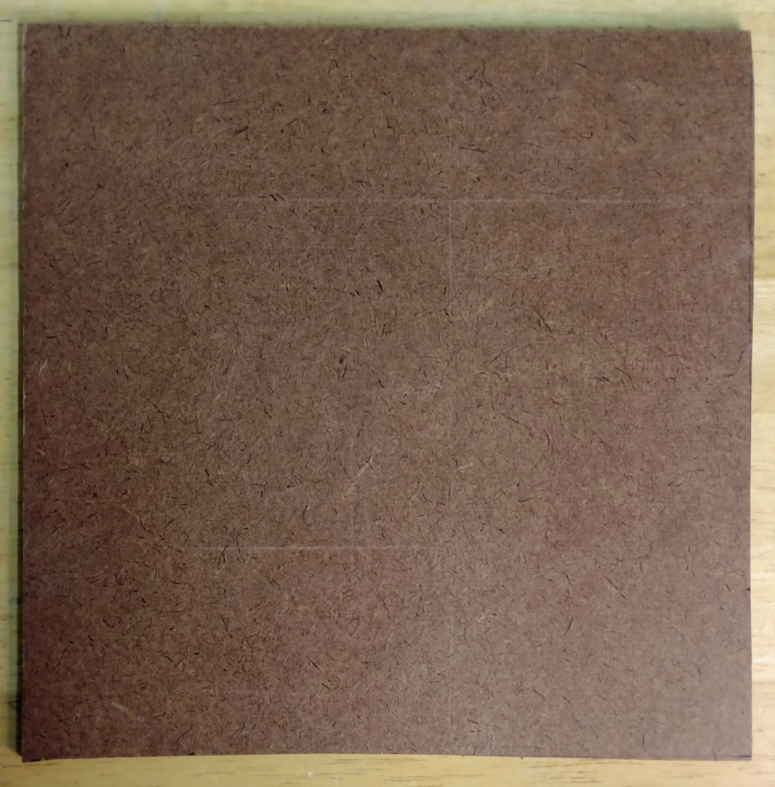
1/4″ Hardboard
Like the MDF core products, this is another one that blew away some of my prejudices. I kind of thought this would disintegrate into splinters and scraps. Originally, I could not find my hardboard and joked about cutting one using some scrap pegboard. However, I did find my piece of hardboard and hacked off a puzzle blank. A quick measurement shows that 1/4″ is really about 3/16″. So, it is thinner than most nominal 1/4″ material.
This product is so different from what I use that I need to include a few photos here. This is the top of the uncut product. It does have a few scratches on it, but they will not impact the final product.
Top of hardboard blank
This is the backside. It is a rough surface, so is useless for bonding images to. You can see it has a repeating pattern pressed into it. I assume other options are available. This stuff really looks like the material my Wentworth laser cut puzzles are made from, other than the rough backside.
Rough backside of uncut blank
I cut the decorative edge and tested the strength of the edge cut offs. As expected, it is a little weaker than most of the plywoods, but not terribly so. The area of the break looks a little different from what plywood looks like.
The broken material from the strength test
It cut very cleanly with minimal fuzz and zero splintering.
Smooth cut edges
Here is a close up of the top cuts. It is the cleanest of any of them.
Very clean cut edges
Here is a close up the sides of the cuts.
Close up of cut edges
Given the texture of the back side, my only option was to paint the top with the acrylic spray paint and leave the back unfinished. From the top, it looks like any of the rest of them.
Painted top
The backside presented a difficulty for me. Because the paint bleeds down the side, it can actually wrap around and suck onto the bottom of the piece being sprayed. If both sides are being painted, this is not a problem, as that side will be painted anyway. In the case of the cabinet plywood above, the backside already had a clear finish on it. This made it easy to remove any errant paint. Not the case for this though.
Paint on the backside
If this puzzle had an image on it and were cut out as normal, I would find this to be a very adequate puzzle material. Am I going to switch to using it? No. The puzzles I make are labor intensive and most of the price is from the labor time. Saving a few pennies to use this product would be very counterproductive for my customer base. Most of my customers want a nice-looking puzzle front with a nice smooth visibly appealing wooden back.
Other woods
There are a lot of other woods out there. In my original posts on this issue, I had mentioned making one of these puzzles from construction grade plywood. I am not going to waste my time on that. I would like to sell these puzzles, and I think that product would not make a good puzzle.
Additionally, I have since experimented with three other wood products while making the 2024 Pagey Elliot Puzzle Exchange puzzles. Solid basswood, basswood plywood, and Italian Poplar plywood. I used all of those materials up and do not have any left to make a Dragon Tails puzzle with. I would say all three of those products could be beneficial to a puzzle cutter. They are light weight and very easy cutting. In fact, they are worth considering due to the ease and speed of cutting. Time is money, and most of the cost of a hand cut puzzle is the puzzle cutters time. The downside is that all three of those woods are boring to look at. Just a plain drab white wood. One puzzle maker makes his puzzle wood from solid basswood and attaches his own outer veneer to make a pretty back. That has its own time factor.
Summary and conclusions
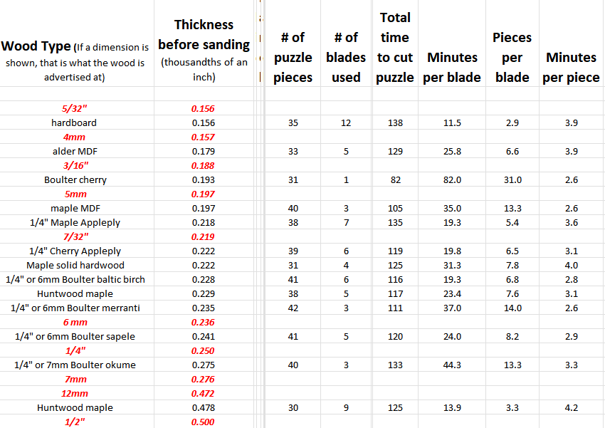
I started this looking for a replacement for Baltic Birch. It seems to me that the quality of Baltic Birch is declining, and it is a boring looking wood. The table below captures some of the data from cutting these puzzles. There are some inconsistencies that do not make sense in the numbers. For example, why did the MDO alder core take longer to cut than the MDO maple core when the alder product is thinner? It also took more blades for fewer pieces. The sample size is just too small to really be accurately meaningful.
However, some valid observations can be made. The hardboard used the most blades and took the longest to cut. This makes sense, as it is comprised of a lot of resins and glue, which are hard on blades and cut slower. The harder plywoods (Appleply, Baltic birch) took more blades and more time.
I had previously determined that the single ply cherry product from Boulter and the Meranti plywood were totally unacceptable for my use.
I would add the hardboard to this category. I think it would make a decent puzzle material for personal puzzles. It actually would make good puzzles period, but I think for a high-end customer it would not be desirable.
I was really surprised by the veneer peeling problem with the cabinet grade plywood. I have used the 1/2″ thick stuff for numerous puzzle projects over the years and not run into this. The difference is that I have mounted an image on the bare side and cut those puzzles with the finish side down.
From the rest, I pick Appleply as my first choice. It has some drawbacks in that it does take more blades and a little longer to cut.
Second choice would be if I could find some MDF core product with a nice outer ply that is thicker than the two samples I used. After sitting down to assemble a number of these in one sitting, the MDF core puzzles were noticeably thinner. The okoume and sapele would also be good choices. The MDF is very flat and easy to cut.
Baltic birch remains an easy backup. It has been easy to source locally.
I would still like to find some lightweight wood that has a nice outer veneer surface on it.
If I did this over, I would choose a different piece style. These dragon tail pieces individually take way too long to cut for a project like this. Additionally, I ended up cutting 18 of them, which is a bit of a sales problem. Due to the amount of time it takes to cut them, the price per piece is high. Although unique looking, they are admittedly spendy for what you get.
In August, I started a puzzle for a customer. It was a print she ordered from a website and sent to me to cut into a puzzle. I started cutting but had some problems with the outer veneers of wood separating from the plywood. I had to order a new print and start over. I ended up ordering a slightly larger print so I could have more freedom with customizing the edge of the puzzle while still keeping close to the goal of 430 pieces.
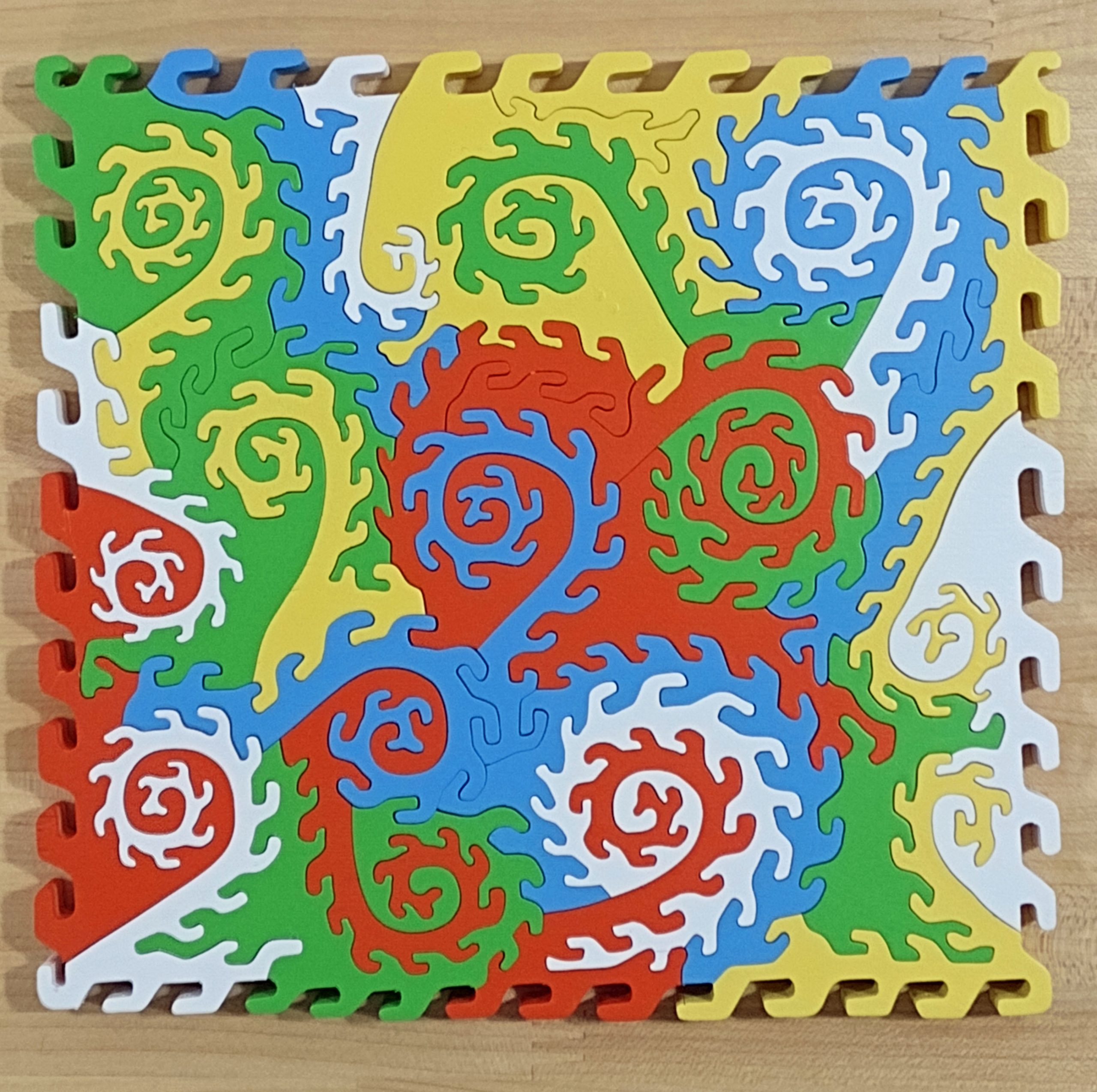
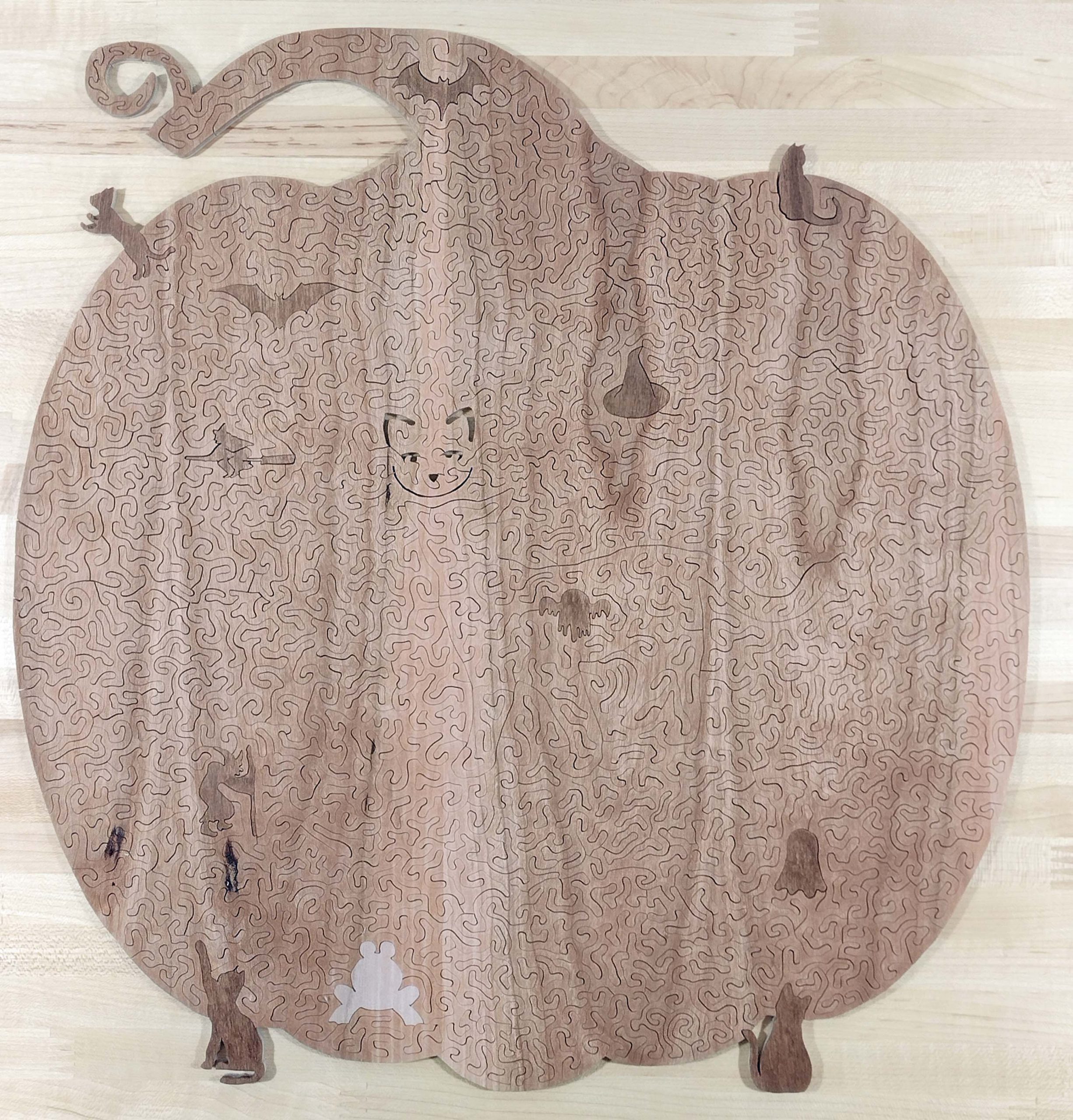
It is a beautiful print, entitled “Rainbow Heart Kitty” by Laura Iverson. It is quite colorful and seemed to me to beg to be treated as a Halloween related puzzle. So, I did. It has cat figurals as well as some bats, ghosts, and witches. Here is the finished puzzle. I finished cutting it at the end of September and shipped to her in October.
Puzzle cut as pumpkin shape
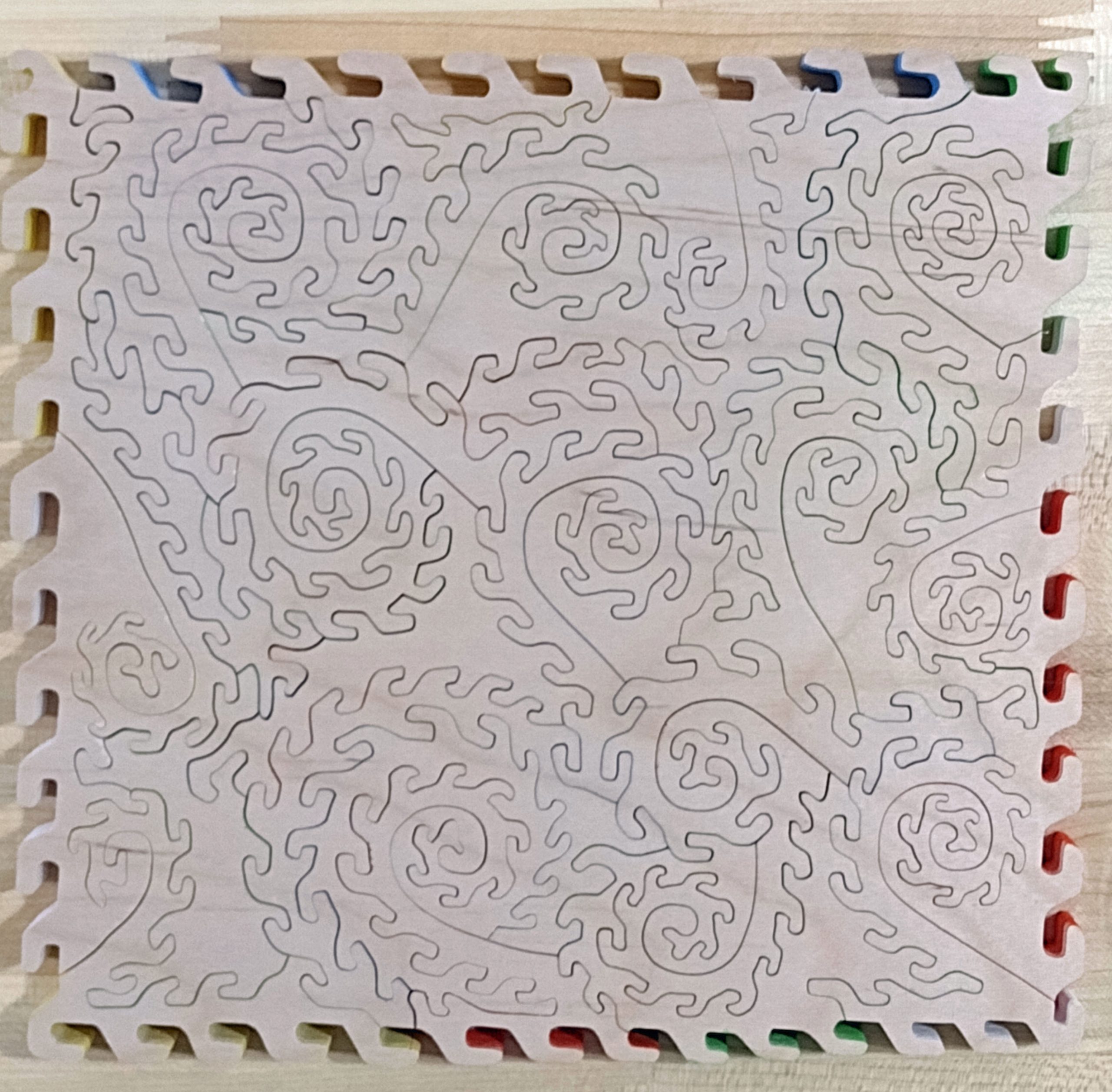
The back of the stained puzzle. I did not stain the signature frog piece and had not yet annotated it when the picture was taken.
Back of finished puzzle
Here are some close ups.
Relief cuts to make a face
Front of relief cuts
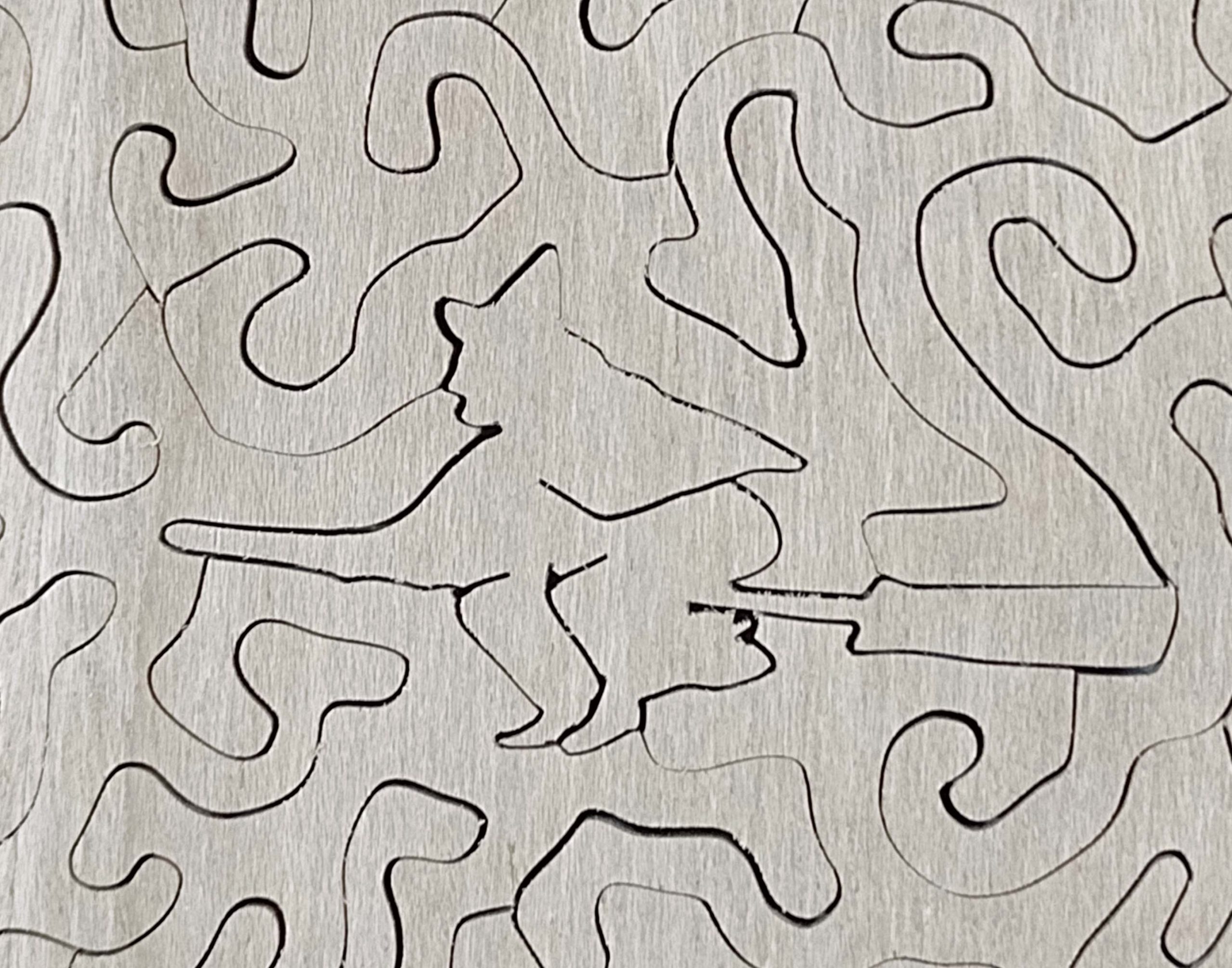
Witch with a staff
Witch on a broom
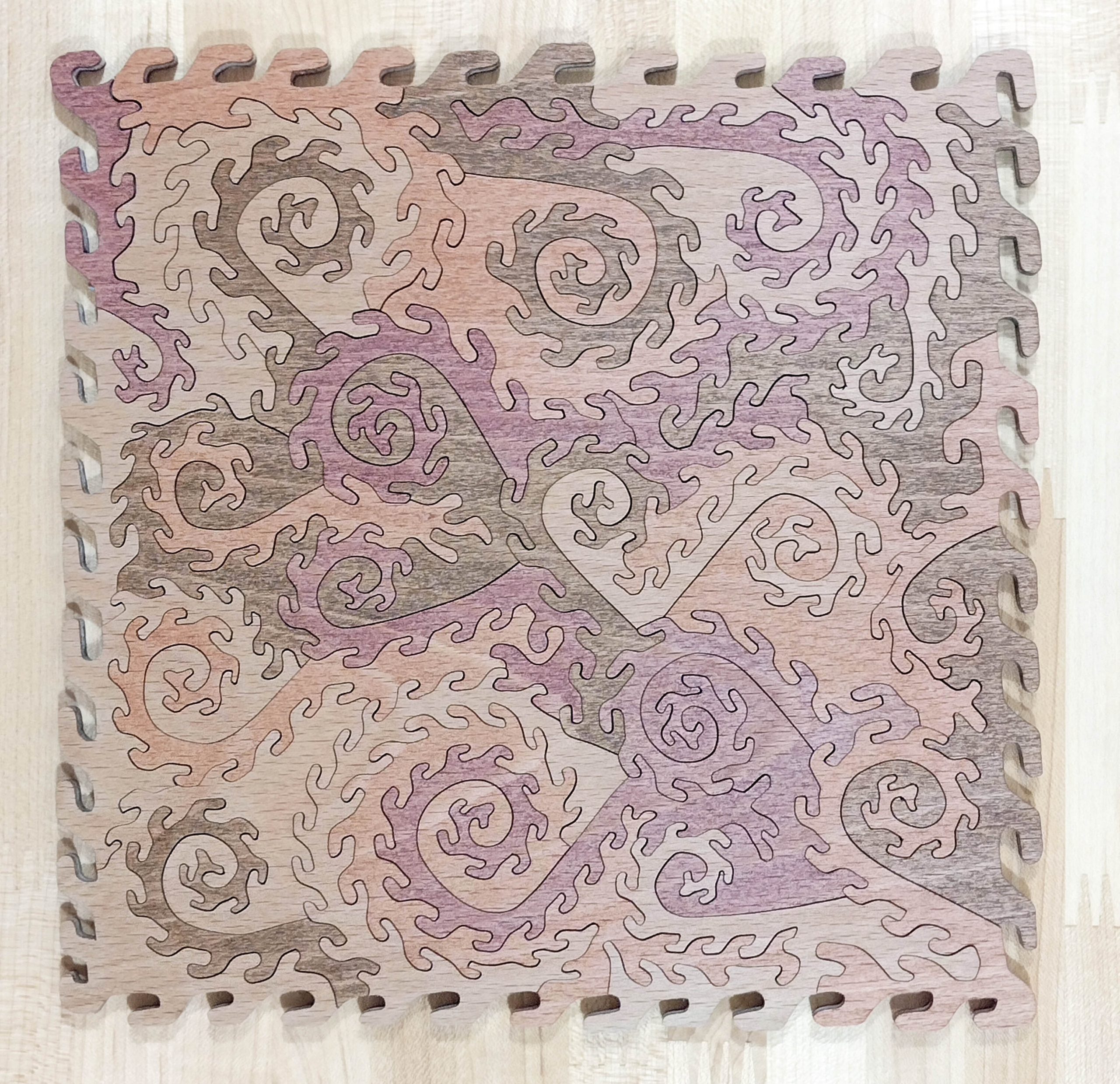
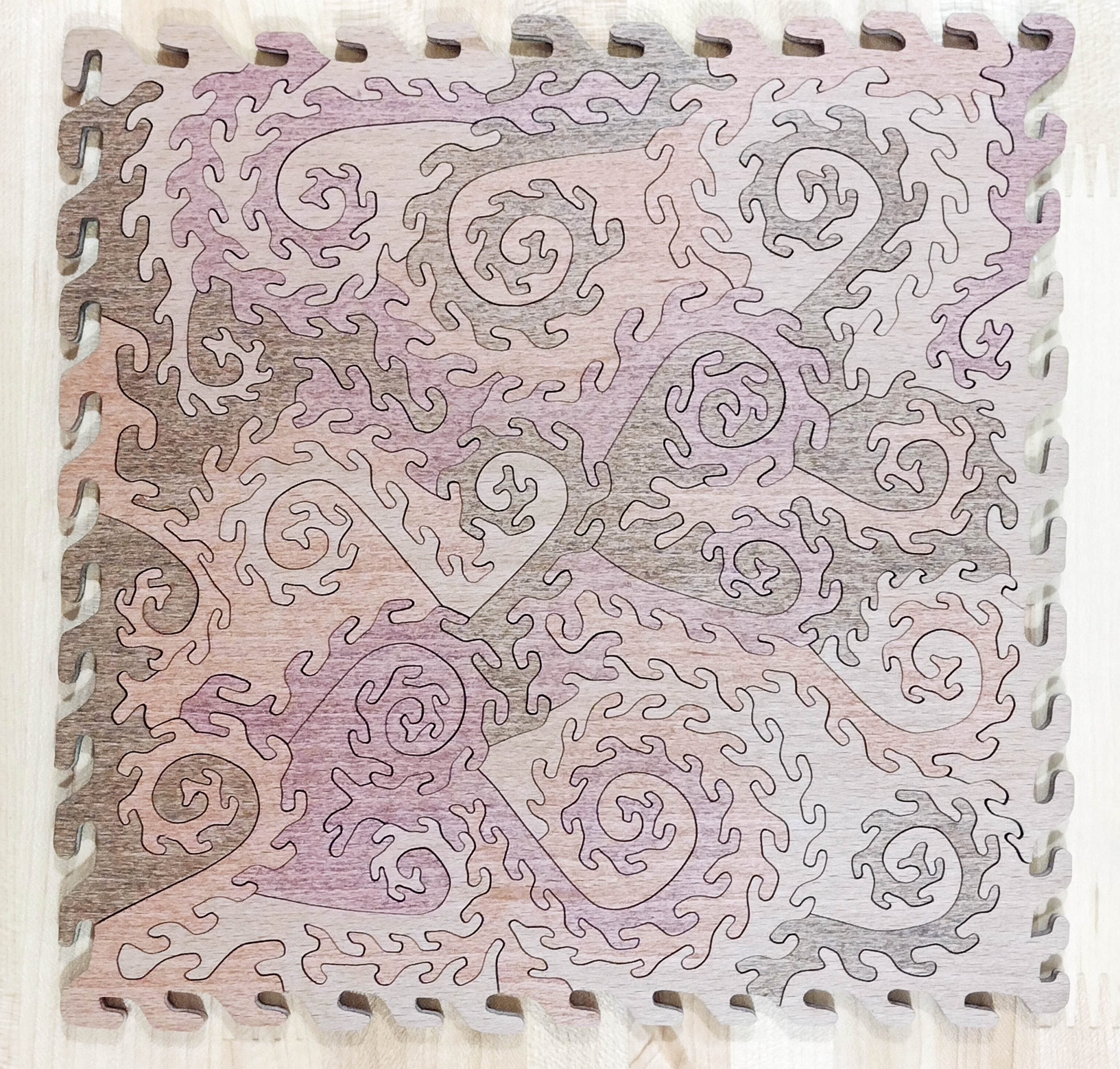
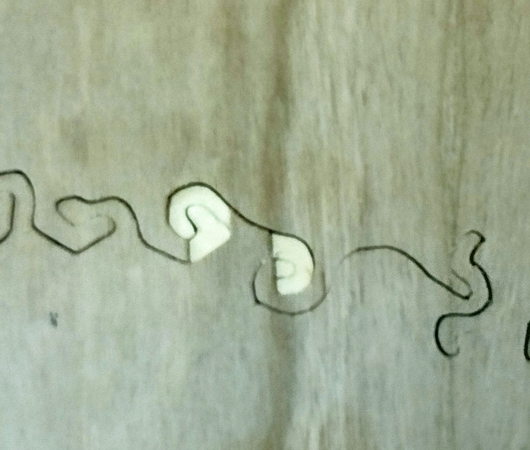
Originally, the puzzle shape was going to be different. Here is what it was before the veneer started peeling off.
Original puzzle
I like the finished product much better than the first plan.
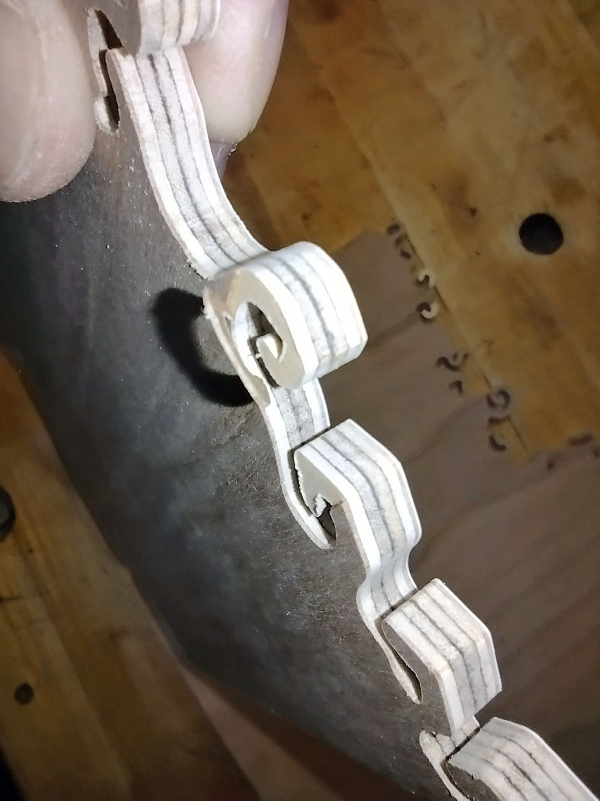
Here is some of the veneer delamination I experienced.
Veneer delamination
More veneer problems
This issue was a first for me. Hopefully, a last too!
Happy Puzzling!
Bob
Posted inCurrent project|Comments Off on Rainbow Heart Kitty
Not every puzzle order has to be innovative or spectacular in some new way. Sometimes, it might just be a number of small puzzles as a memento to commemorate an event or activity.
I was corresponding with a client about a custom puzzle she wanted cut. In the discussion, it came out that she was a new author with her first book coming out soon. She wondered about maybe making a puzzle using the book cover art. I instead suggested she make some small collector card puzzles for a book signing or whatever similar function that might be happening.
She was interested in pursuing this concept but wants to hand them out as gifts to her editorial and publicity teams. She forwarded digital files of the covers. It turns out the U.K. version of the book will have a different cover from the U.S. version of the book. If you might be interested in the book, the pre-order link is here: Notes-On-Surviving-the-Fire-by-Christine-Murphy. Christine Murphy is a member of and comments in some of the wooden puzzle groups on Facebook.
Here is the U.S. version of the book cover:
U.S. version
Here is the U.K. version of the book cover:
U.K. version
Due to the geometry of the covers, we settled on puzzles that were 2″ x 3″ and had approximately eleven pieces in each. That let me print 12 of each cover on an 8 x 11.5 sheet of photo paper.
I printed out 12 of each cover and mounted them on cherry Appleply. Once cut out into individual puzzle blanks, I then cut them up into pieces. After sanding the backs, I applied a neutral Danish finish oil to pop the grain out a bit.
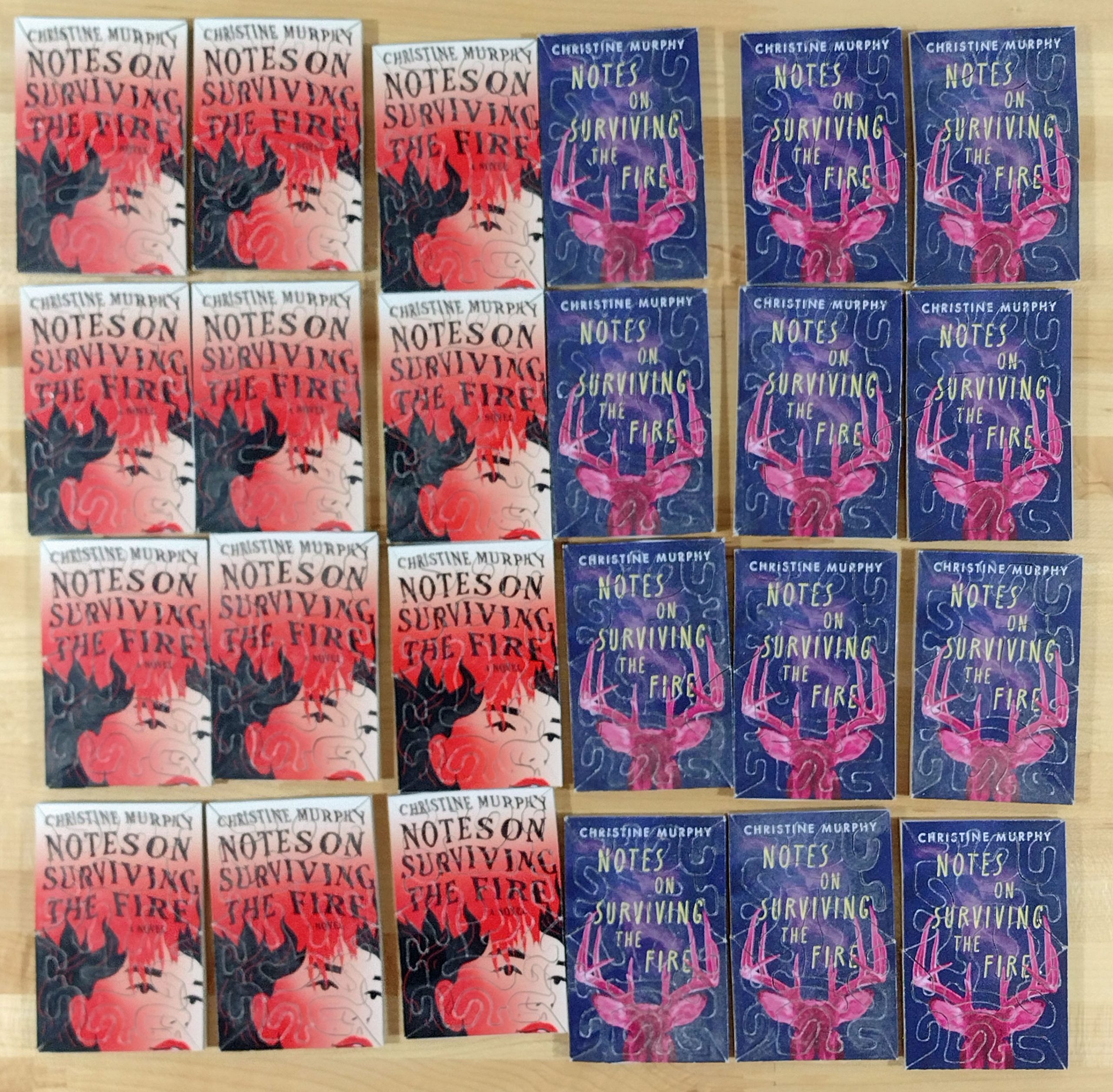
These are the fronts.
Fronts of puzzles
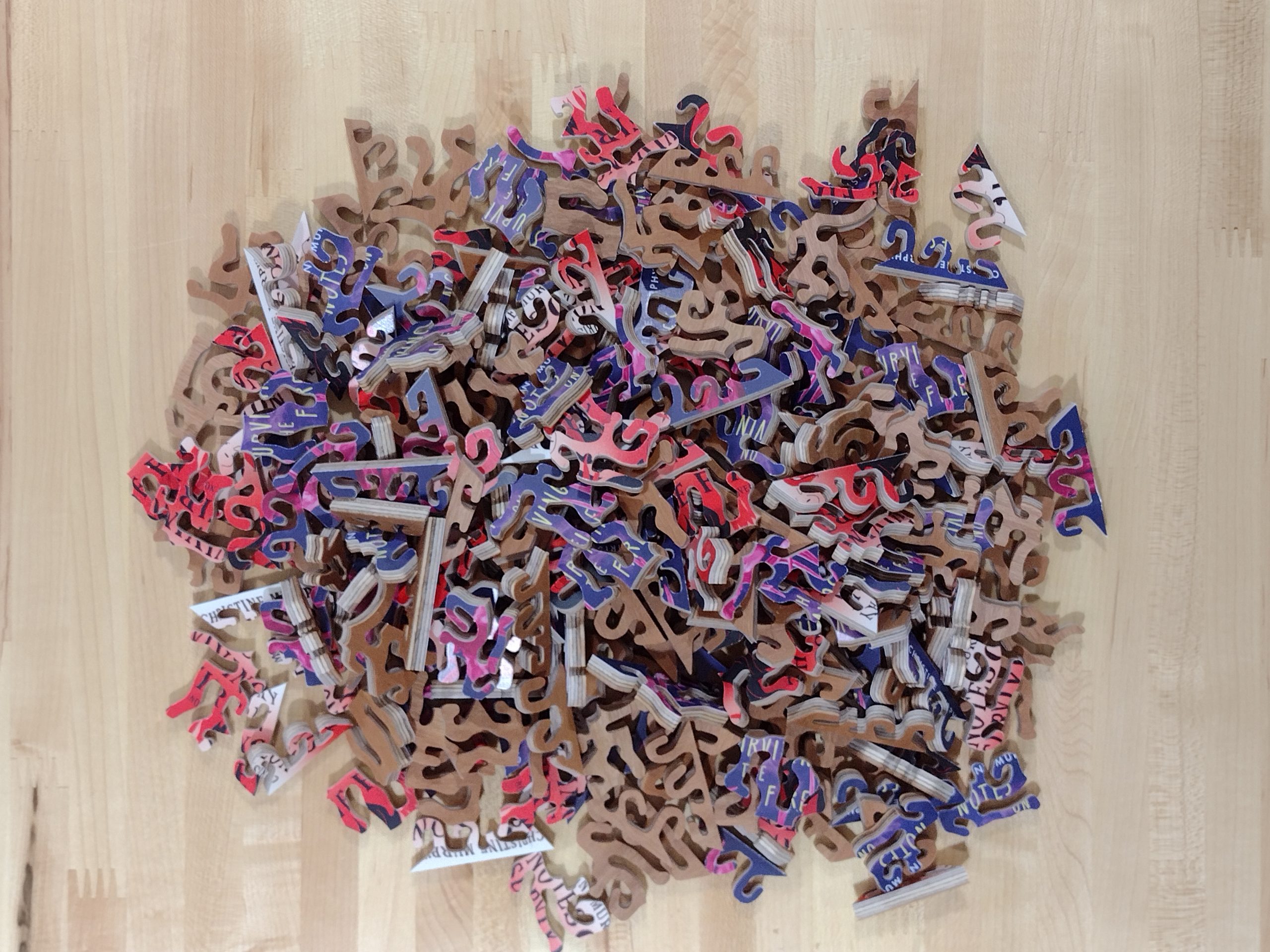
She wanted them delivered taken apart so that she could assemble them before handing them out.
Pile of 264 loose pieces
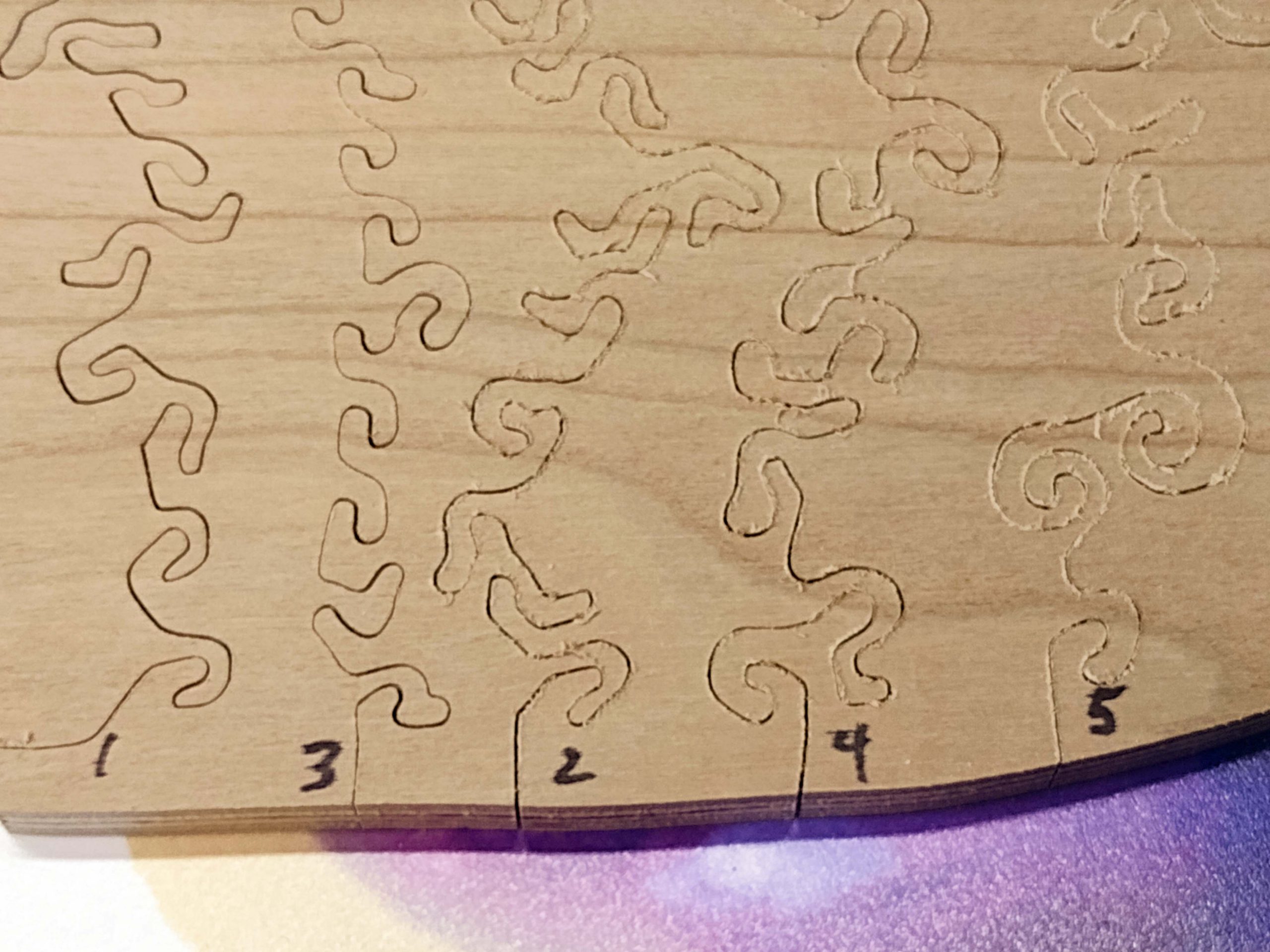
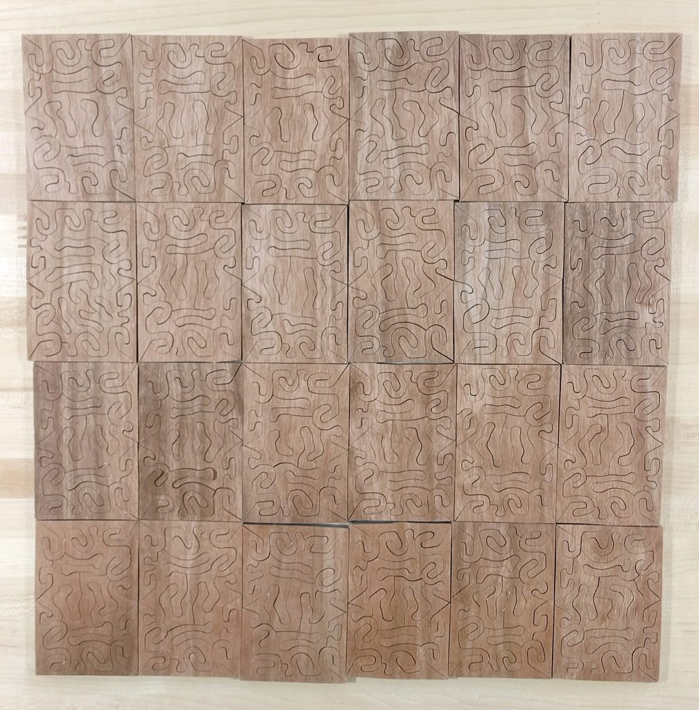
She now has a pile of pieces that are 12 similarly cut puzzles for each book cover. That might be a challenge! If you look closely at the backs, each little mini puzzle is cut out using a similar pattern. When cutting these small business card puzzles, I found it is easier and quicker to fall into a repetitive pattern while cutting the pieces. Kind of like shifting gears in a manual transmission. There is only one below that is significantly different. That was the first one I cut, and I settled on a simpler pattern for the rest of them. Still eleven pieces each. Six edge pieces and five inside pieces. Or maybe four edge pieces and seven inside pieces. It depends on how you count the pointy middle edge pieces!
Puzzle backs
I recently attended the 2024 Puzzle Parley and made up sixty “business card” or “collector card” puzzles as give aways. These were 2″ x 2″ and had seven pieces each. I also made 96 similar ones for Puzzle Jam South last summer.
Uncut collectible puzzle
Nothing exciting from a puzzling standpoint, but a nice give away that is a form of advertising. I have a little three piece one that was sent to me by Stave Puzzles years ago. It sits next to my computer for some reason. I sometimes pick it up and wiggle it around while staring at the computer screen in thought. The cut edges are finally starting to peel or delaminate a little bit. I suppose I should get a fidget spinner or something similar to keep my hands busy while pondering whether or not 42 is truly the correct answer.
Happy Puzzling!
Bob
Posted inCurrent project|Comments Off on Something A Little Different
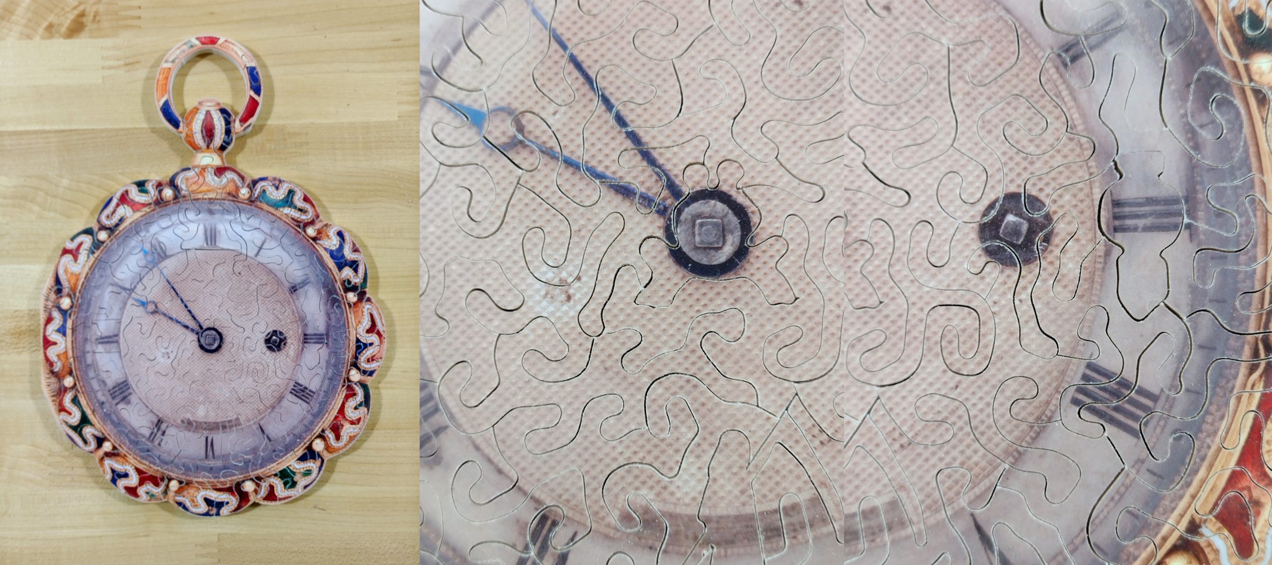
Second Challenge – reducing or preventing tear-out roughness on the backside
Once the alignment issue was resolved, next was to reduce the amount of tear out on the backside of the puzzle. At first, I attempted to do this by experimenting with different brands and styles of blades. Blades are sized by numbers. 1 is smaller than 3 which is smaller than a 5. If you want smaller than 1, you see numbers that look like 2/0, which is spoken “two-ought”. Now as the numbers get bigger, the blades get smaller. 3/0 is smaller than 2/0 and so on. All of my 1/4″ thick puzzles are normally cut with 2/0 or smaller blades.
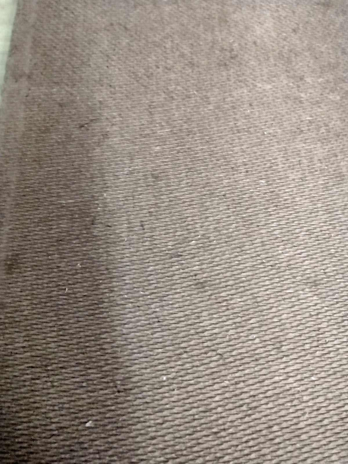
As the blade moves up and down on the wood, the teeth are typically pointing down at the table. The sharp tip of the blade cuts through the wood, leaving a smooth top side. On the bottom, that sharp tooth pushing out of the wood causes the bottom edge to tear out, leaving a felt roughness. With a wooden backside, that is no problem. When the puzzle is done being cut, you do some light sanding to smooth it out.
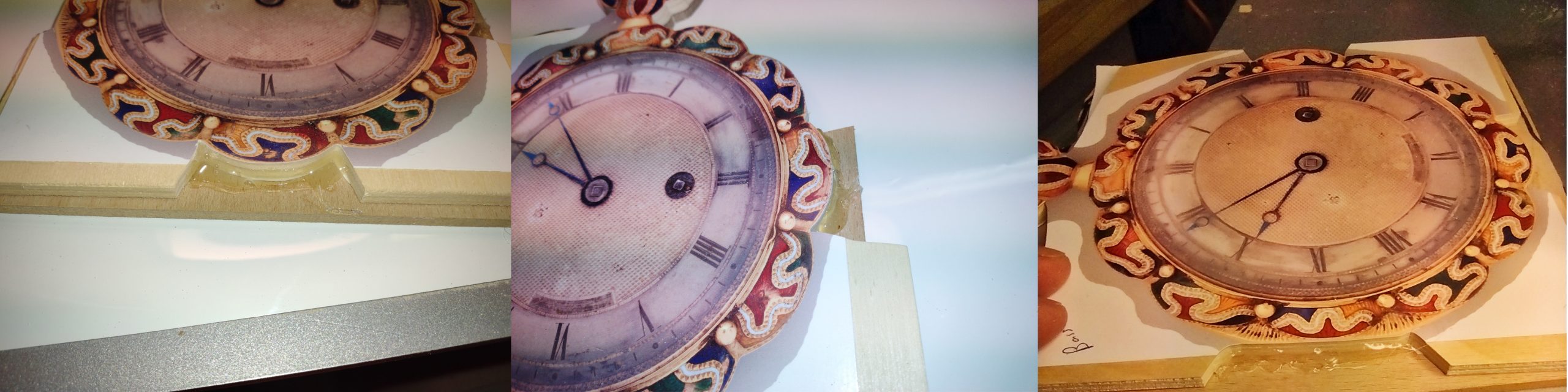
The first puzzle I cut (shown in my last post) was cut with Pegas MGT 2/0R blades. The “R” in 2/0R means the bottom section of teeth is reversed so they point up rather than down. This can give a very smooth bottom cut, depending on where the table sits relative to the blade. In this case, they did not give a smooth cut.
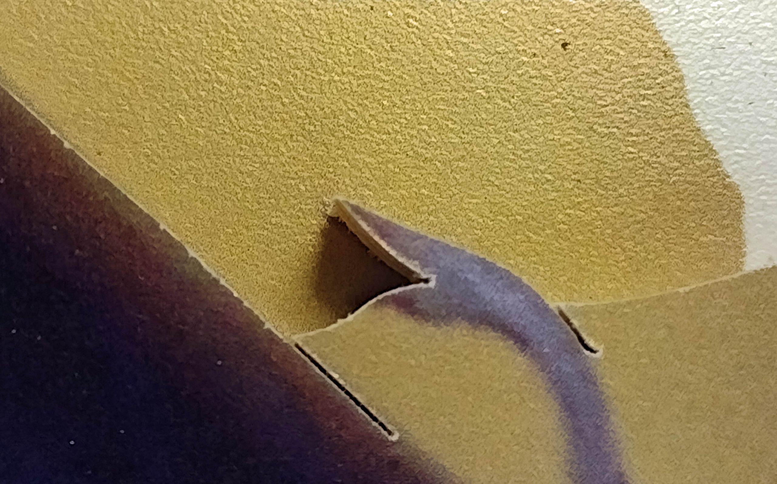
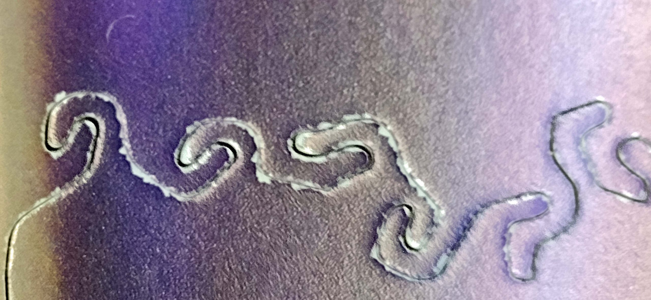
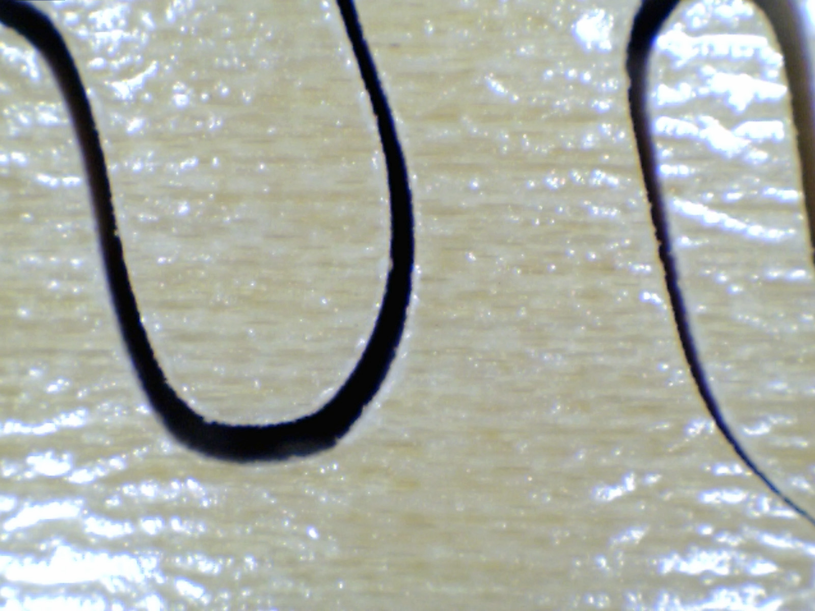
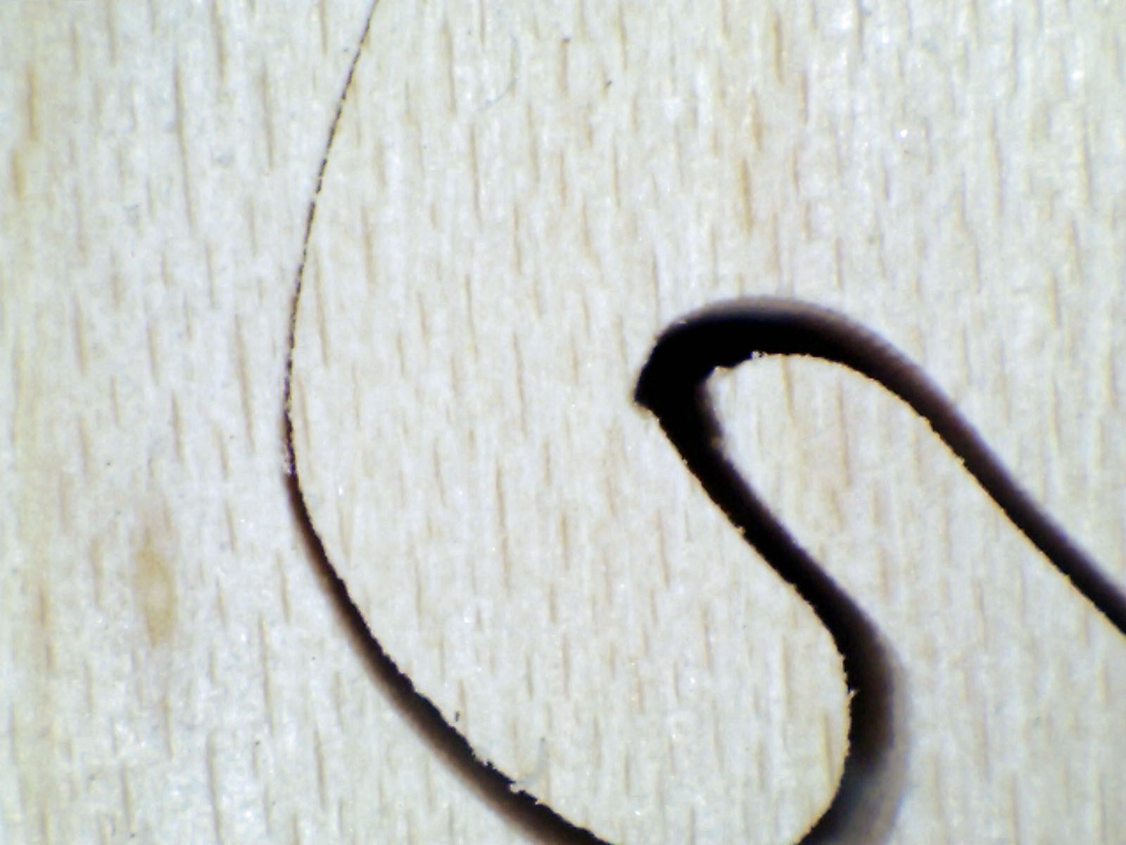
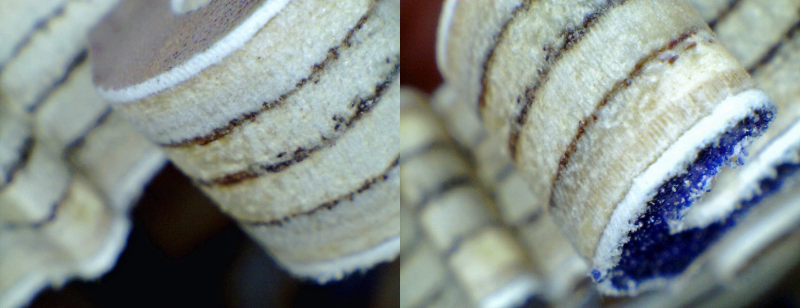
In the highly magnified picture below, the left-hand image shows the top of one of the pieces. The top edge of the cut is nice and smooth. The cut is very crisp. That same piece is then rotated a little bit to view the bottom of the piece. You can see how rough it is in the right-side image. The photographic paper is torn and curling away from the cut. When the puzzle is assembled, that backside has a rough feel to it.
Piece cut with Pegas MGT 2/0R blades
I tested about 12 different brands and styles of blades. I ended up cutting a total of five puzzles while experimenting with blade types. I found one blade that was noticeably better than the others (for this purpose!). Notice I said better, but not good.
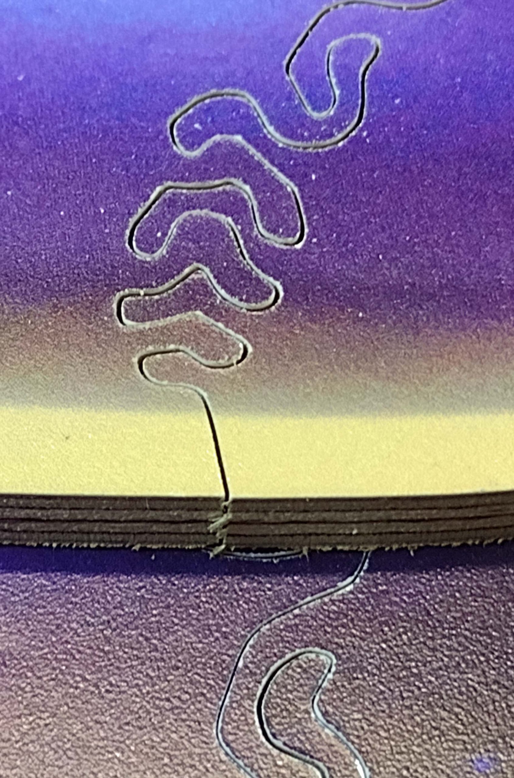
The blade I found to give the smoothest cut on the bottom side was the Flying Dutchman 2-Way Cut blade. (I am abbreviating these as FD TC blades.) It has two teeth down and one tooth up, repeated the entire length of the blade. The negative part is that you have teeth pointed up coming through the top of the cut, giving a little rougher cut on the top. Here is a drawing of the blade. Flying Dutchman has another very similar blade called the Flying Dutchman Ultra Reverse (FD UR). It has the same tooth arrangement but costs a little more. I did not find a significant difference between the FD TC and the FD UR blades.
Profile of Flying Dutchman 2-Way Cut blade
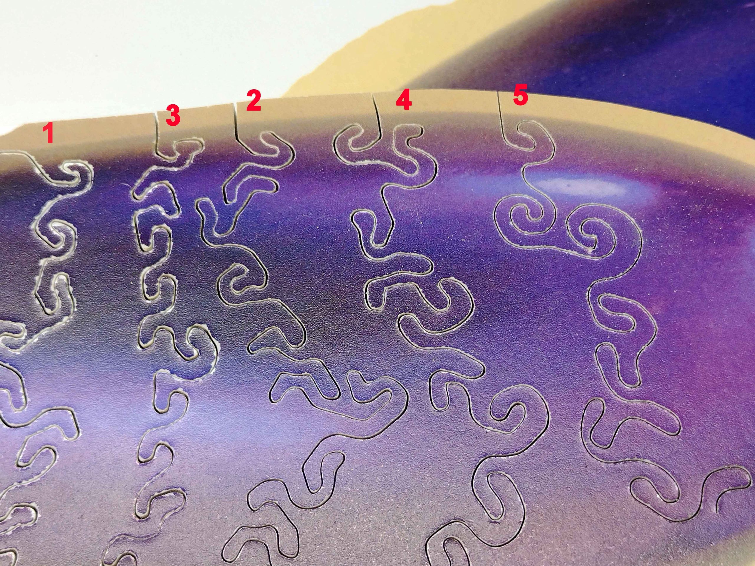
Here are some images of the cuts on one of the test puzzles using three different blades with no other tear-out prevention measures.
Three blades compared left to right: Pegas MGT 2/0R, FD TC, FD UR
After these five puzzles, I was getting a little frustrated. I was pacing around the shop and happened to look over at my table saw. Bam! Right there was the answer for me: a zero clearance insert!
Table saw zero clearance insert
When cutting wood on a table saw and you want to minimize the splintering, you place a new blank piece of wood in the throat on the table, and then slowly raise the spinning blade through that new piece of wood. This causes the wood to be very tight around the blade and provides support to the underside of the wood being cut. This reduces splinters. (They do need to be replaced periodically as the blade slot gets wider and wider with use, like the one above.) Now how to do that with a scroll saw? As you can see below, the scroll saw has a rather large hole in the table with no allowance for making zero clearance inserts.
Scroll saw lack of zero clearance
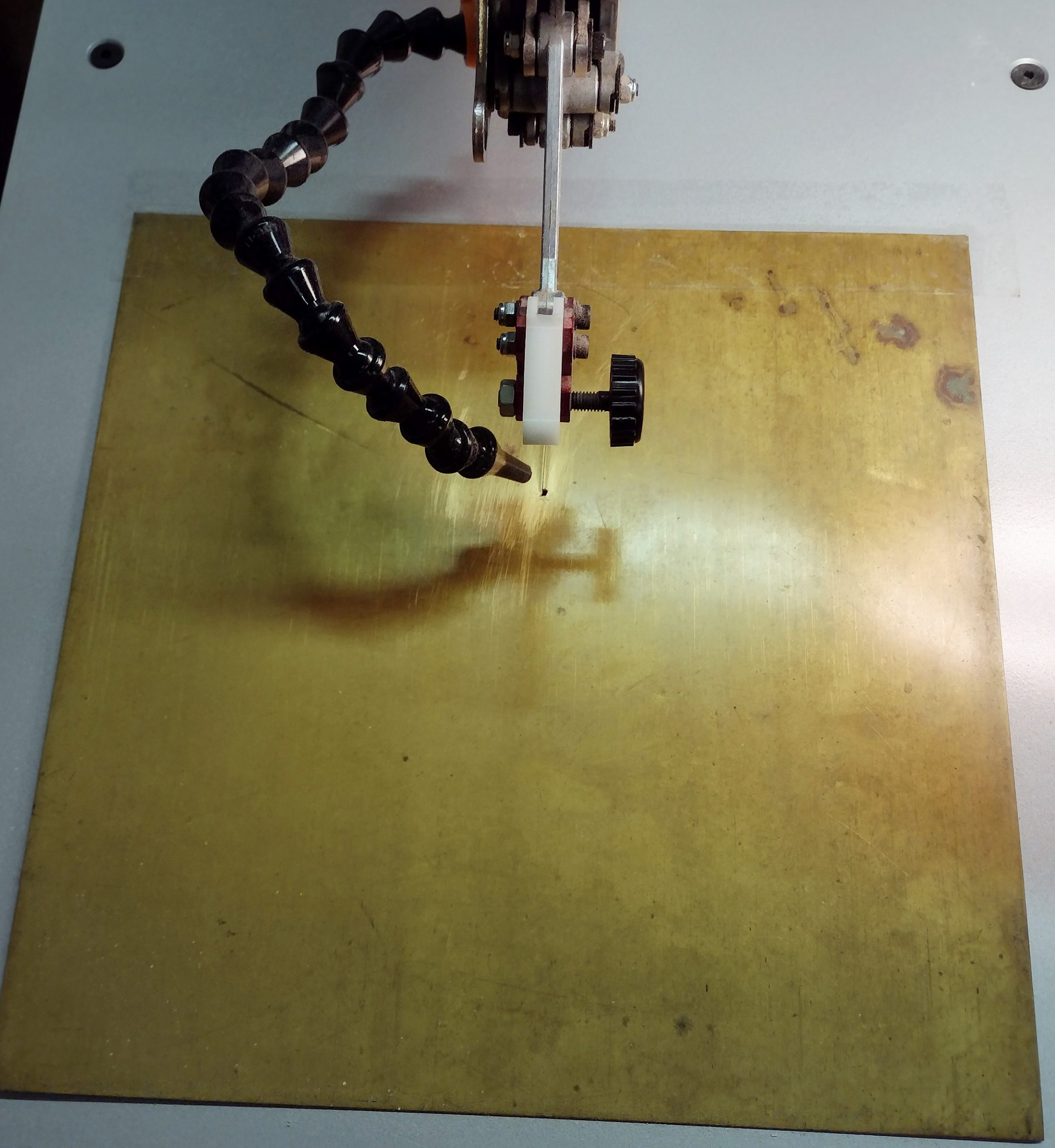
I happen to have some 12″ x 12″ sheets of brass stock. I am not sure what they were originally intended for, but I use them for getting signs/plaques engraved and for shim stock. I took one and cut right down the center of it until I was part way in. At that point I taped it down to the table.
Brass “zero clearance” plate for scrollsaw
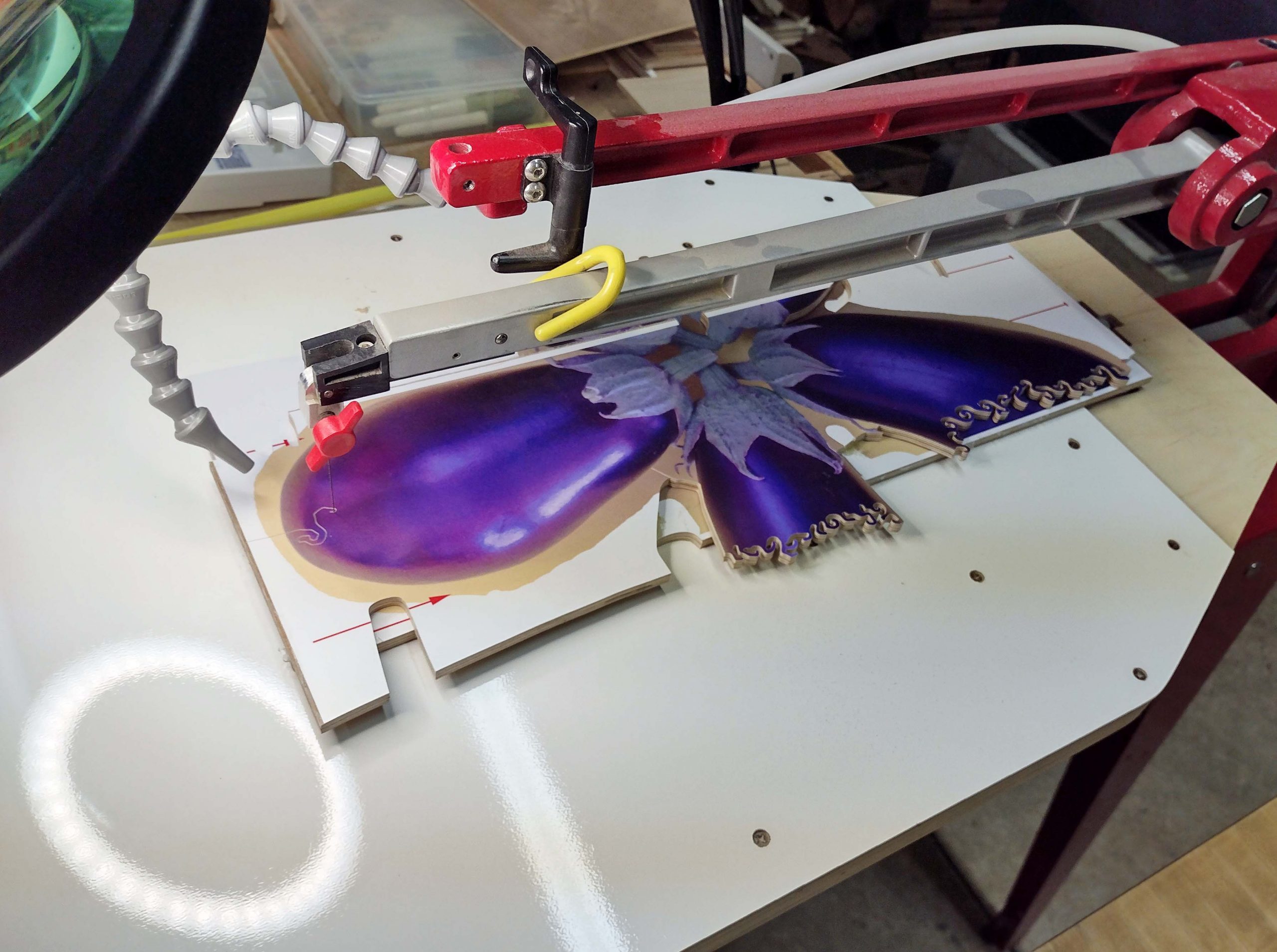
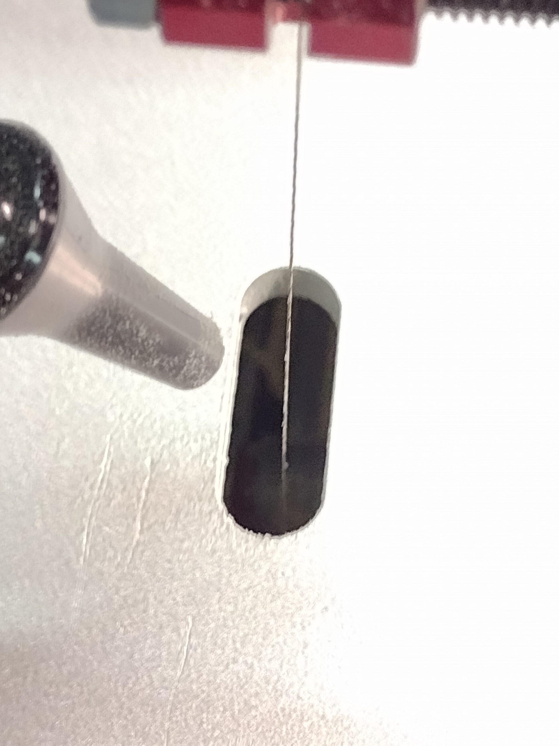
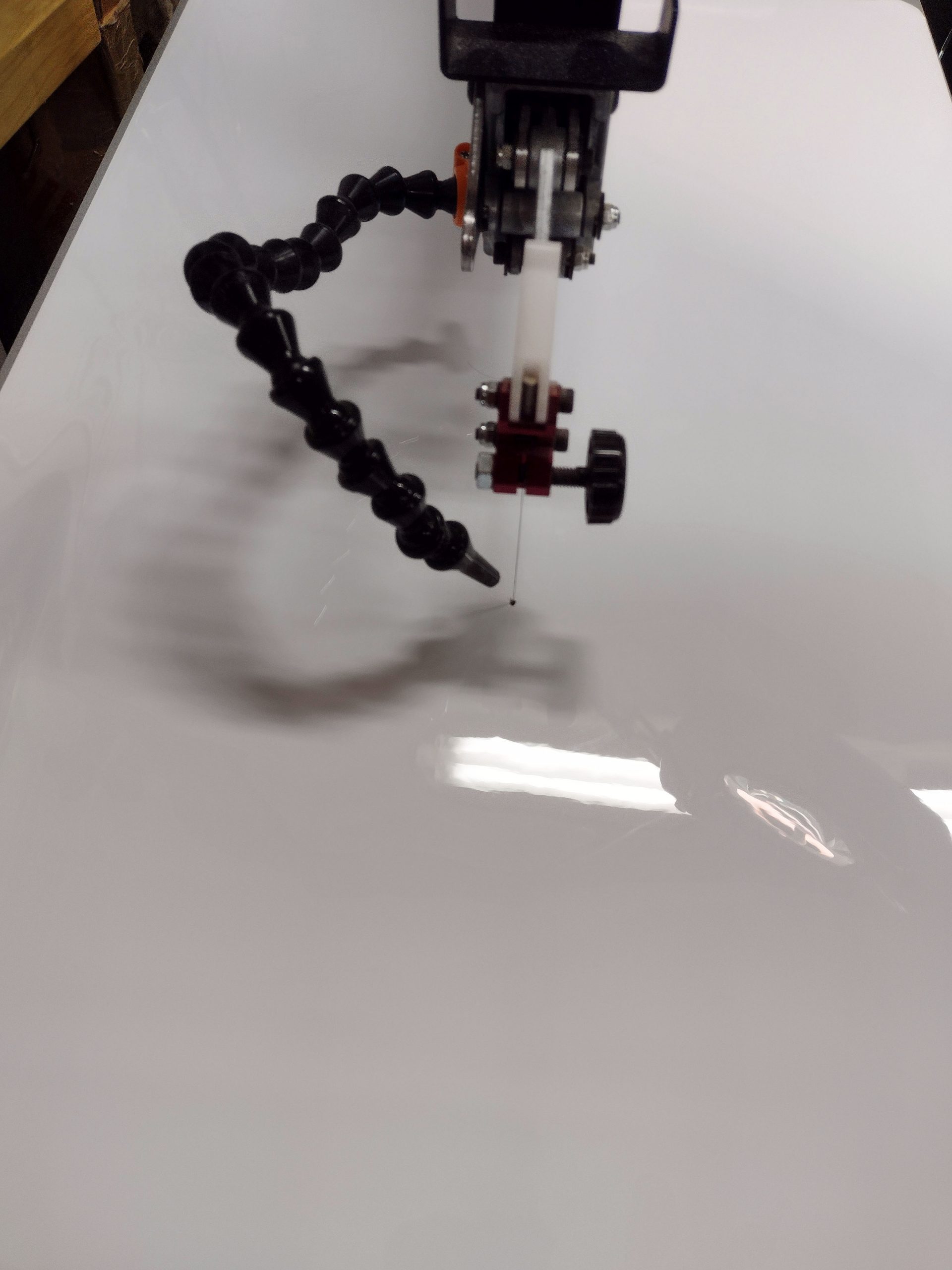
Now we are talking! I started cutting another puzzle. As I cut, one problem rapidly became apparent. The sharp edges of the brass were catching on the puzzle as I spun it around, trying to cut/tear the bottom image. That is not good, so I took the next step. I have a large flexible white board that is a refrigerator magnet. It is too soft and flexible to prevent tear out but will work great on top of the brass. I drilled a little hole and placed it over the brass plate to smooth the transition out.
Flexible white board over the brass plate
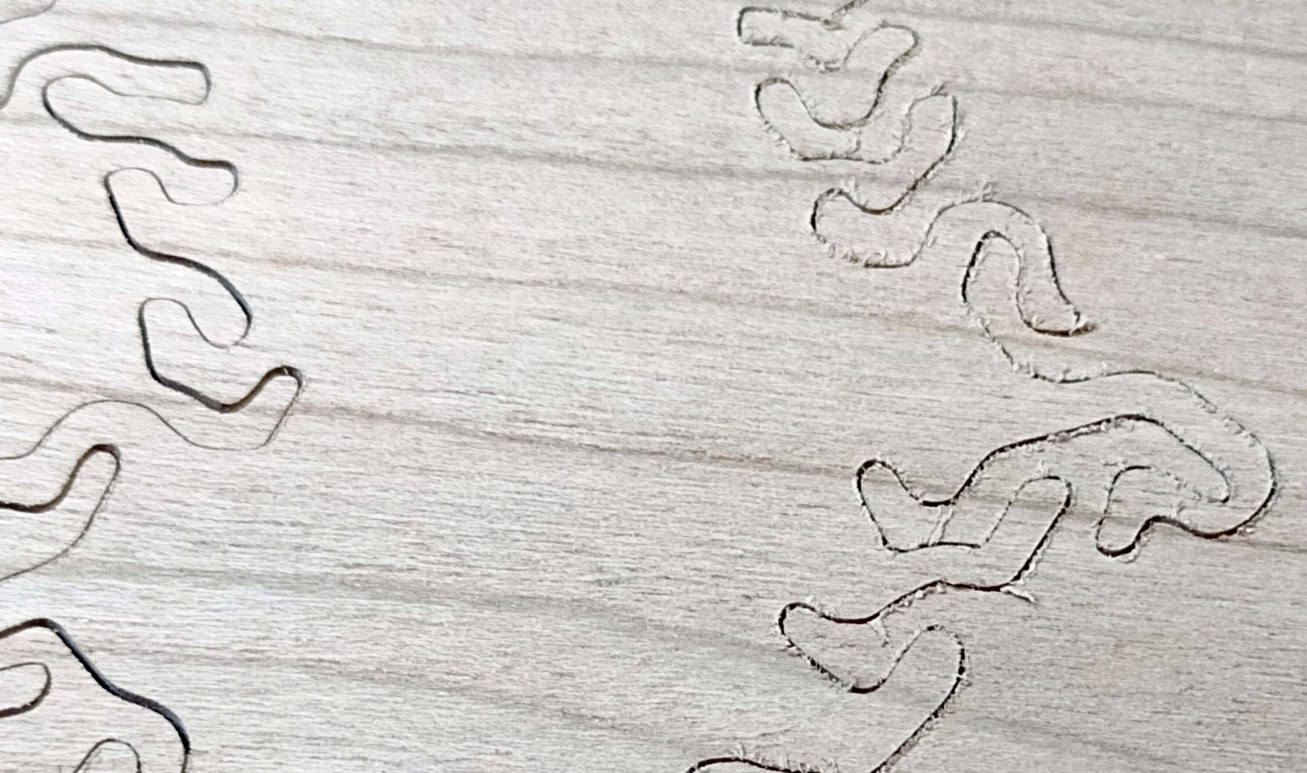
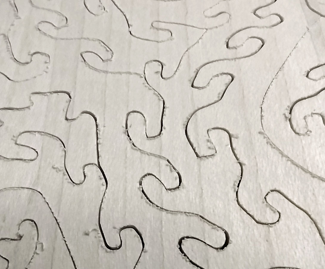
This was a vast improvement! I ended up cutting four of the puzzles I used for the exchange using this zero-clearance plate set up. The image below shows the FD TC cut with the zero-clearance plate on the left, and without the plate on the right. It is a very noticeable difference.
FD TC with zero clearance plate on the left, without zero clearance plate on the right
After the fourth puzzle, I noticed the edges were getting a little more ragged again. This is because the more I cut, the more the side to side and back-to-back movements of the blades made the hole in the brass plate get bigger and bigger. This provided less support to the bottom of the puzzle, resulting in increased tear out.
Zero clearance is no longer zero clearance
So, I had to either replace the brass plate or find another solution. I suppose I could have just moved the brass plate over an inch and made another slot, but that is a spendy piece of material and I did not want to completely turn it into brass confetti by the time I was done. I threw in the towel and did what I did not want to do. I ended up using a piece of sacrificial plywood on the bottom of the next nine puzzles for the exchange.
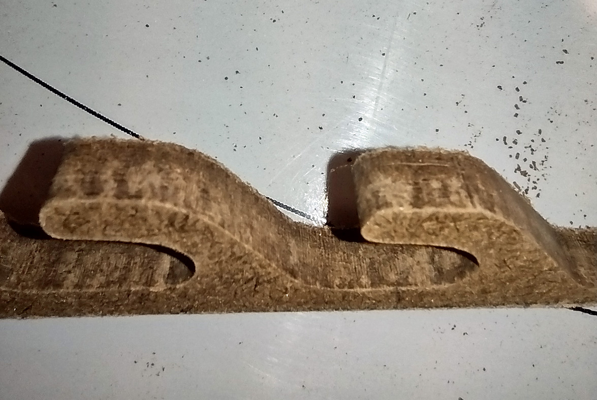
By attaching another piece of plywood as a backing board, it does the same thing as the zero-clearance concept. The saw blade exiting the puzzle passes into the second piece of plywood, which acts as a backing board and prevents the tear out on the puzzle. The second piece of plywood does get tear out, but who cares?
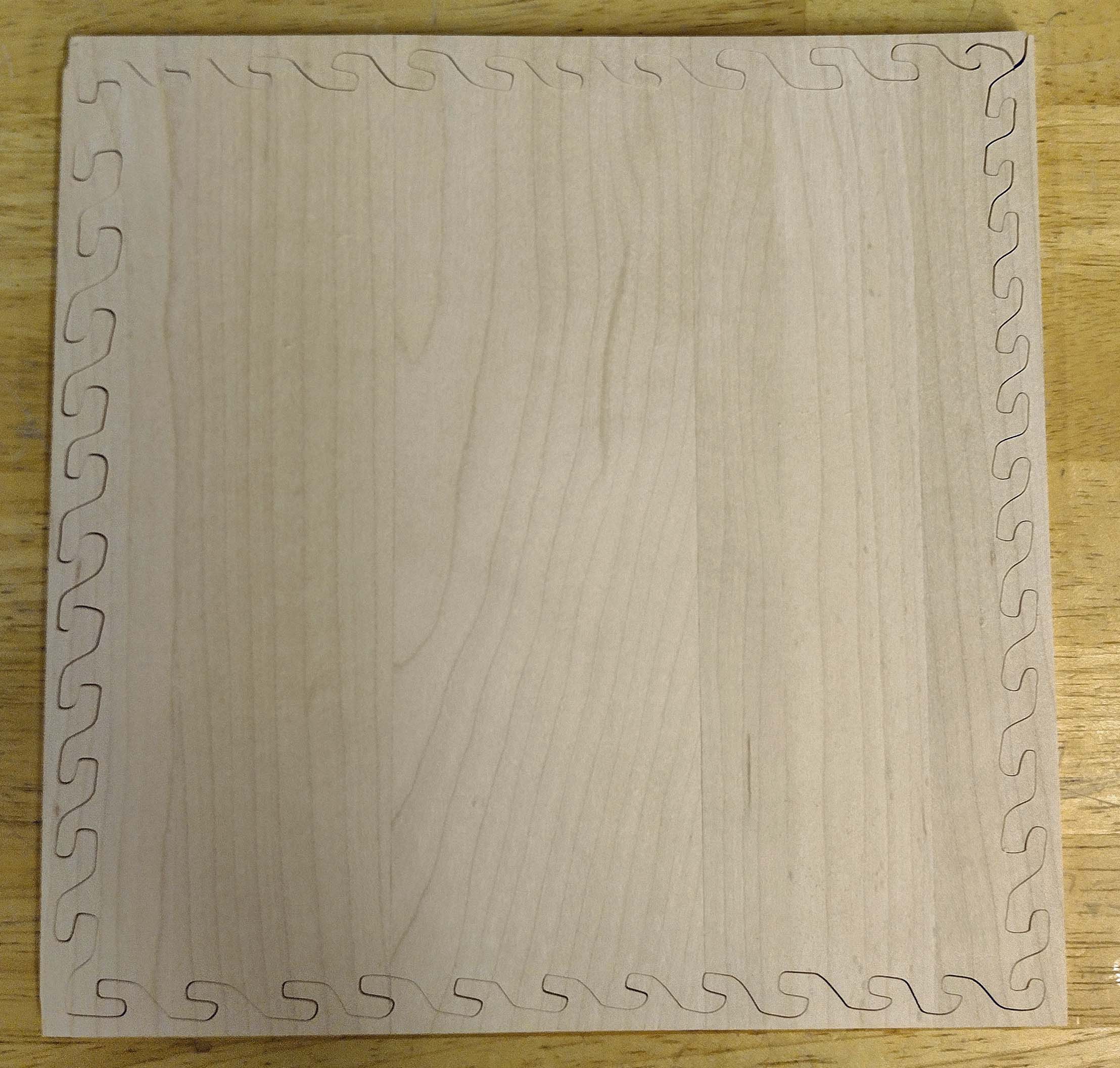
The wood I used for the sacrificial backing board is a thinner MDF product with thin alder veneer layers on the outside. These ended up being puzzles in their own right. Once sanded to remove the tear out whiskers, they can be painted however a person would like. The image below shows how I glued this material with a hot melt glue gun to the puzzles to be cut.
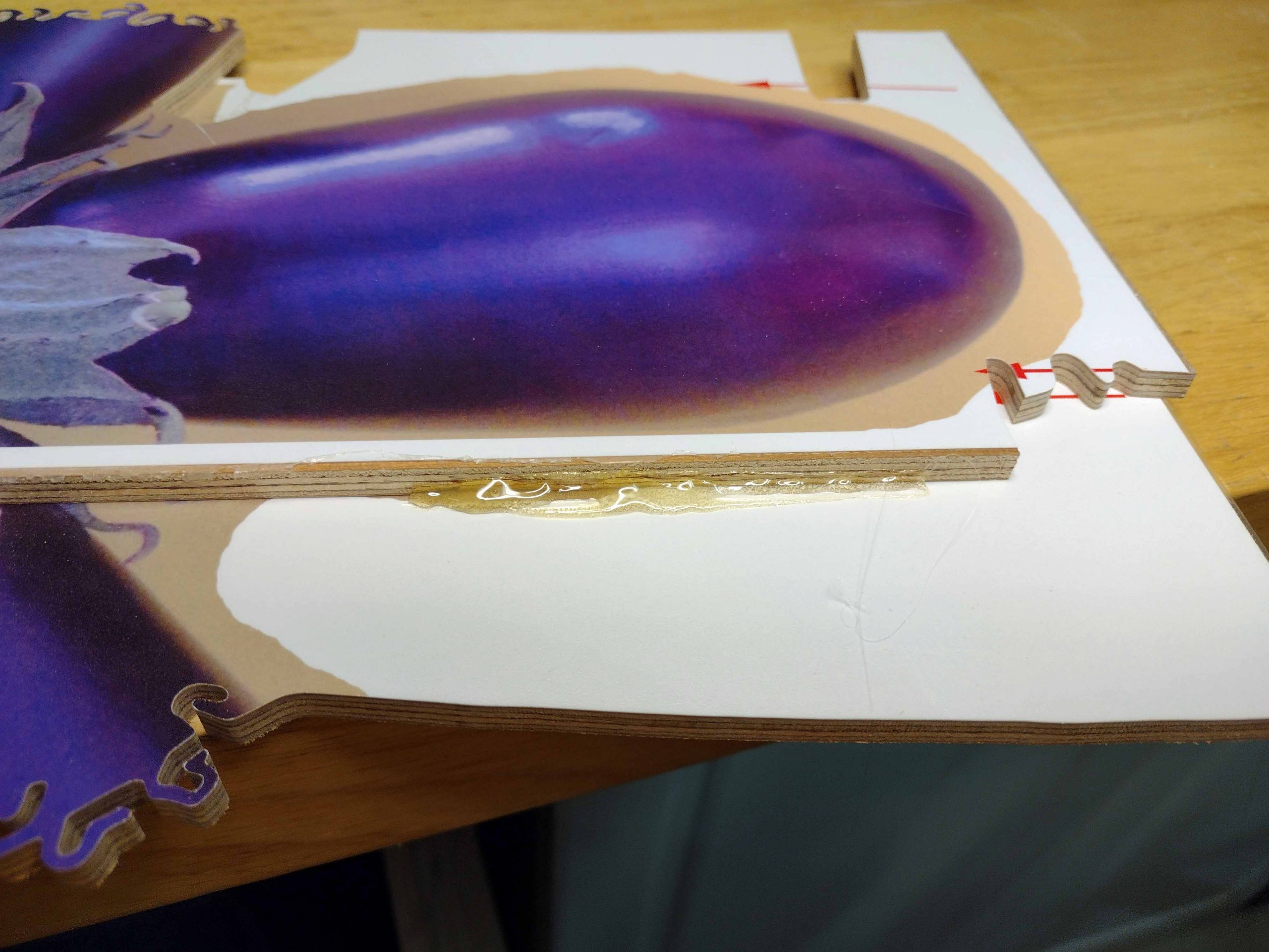
Backing board glued on with hot melt glue gun
As long as the backing board stayed tight against the puzzle board, this gave great results. While gluing the two together, I selected backing boards that matched any cupping or warping in the puzzle board to try and ensure this. The image below shows this tight relationship which resulted in almost no tear out on the puzzle image.
Good backing board
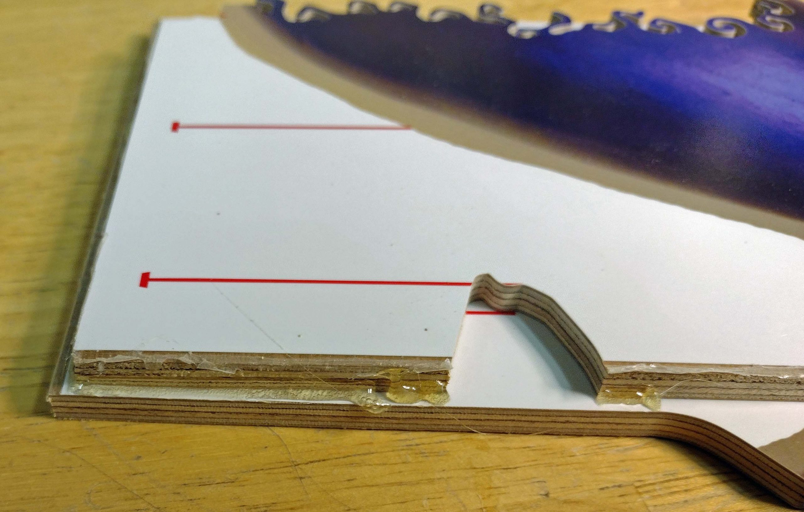
However, as the days went on, those assemblies I had glued up started to expand/contract with the temperature changes in the shop. We went from 70-degree days to 98-degree days with nights getting down into the 50’s. I only cut in the mornings while it was cool, but the wide temperature swings over several days caused some of the assemblies to develop permanent gaps between the puzzle blank and the backing board. This effect would have been reduced if I did not glue up all 9 puzzles at one time and let them set in the heat. Lesson learned.
Gaps developed as the days went on
For these glued up assemblies with gaps, I had to press down firmly to close the gap while attempting to spin the puzzle blank around to cut the pieces out. Pressing down while spinning is not a great thing. It makes it hard to control the cut. On some of these puzzles, my figurals really kind of look a little mangled.
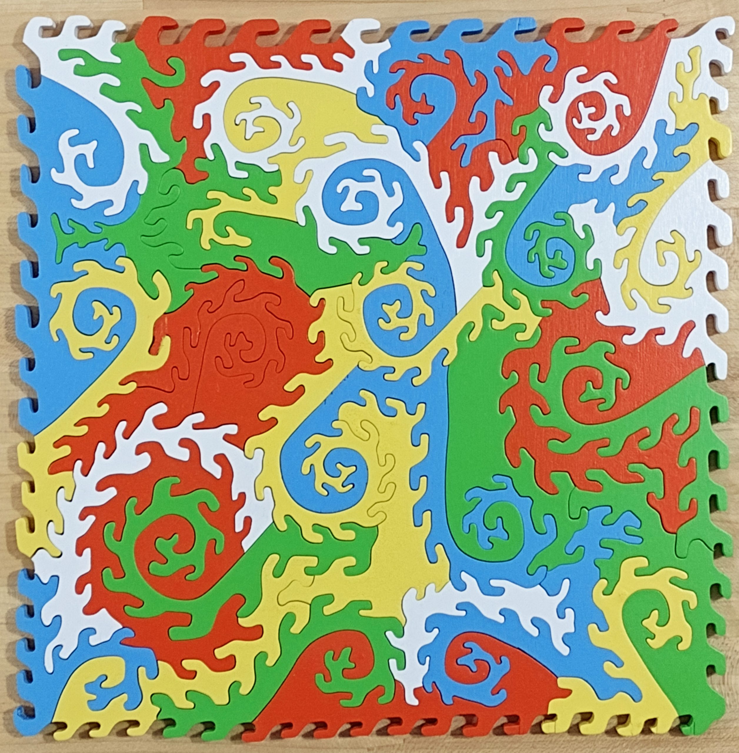
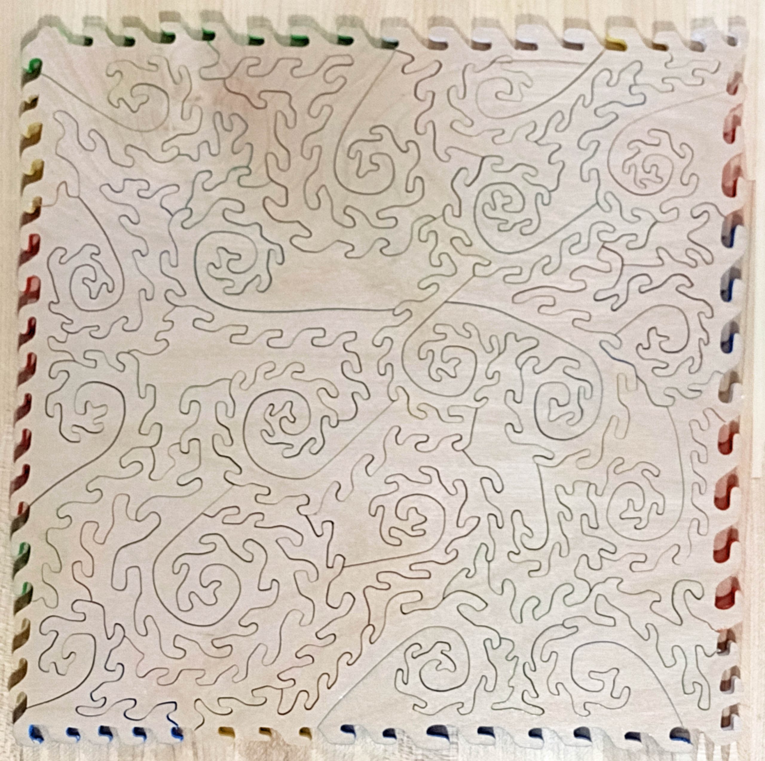
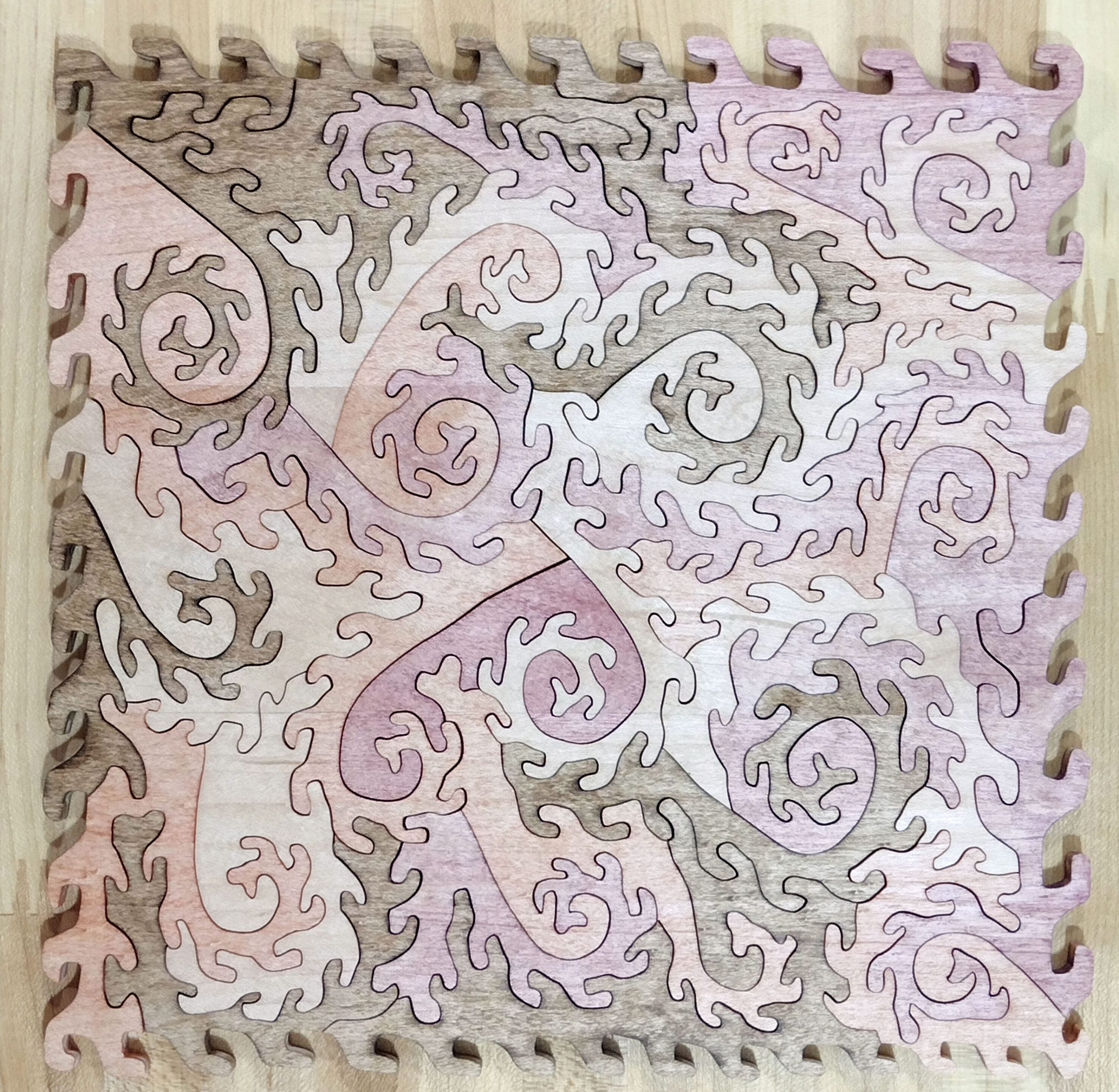
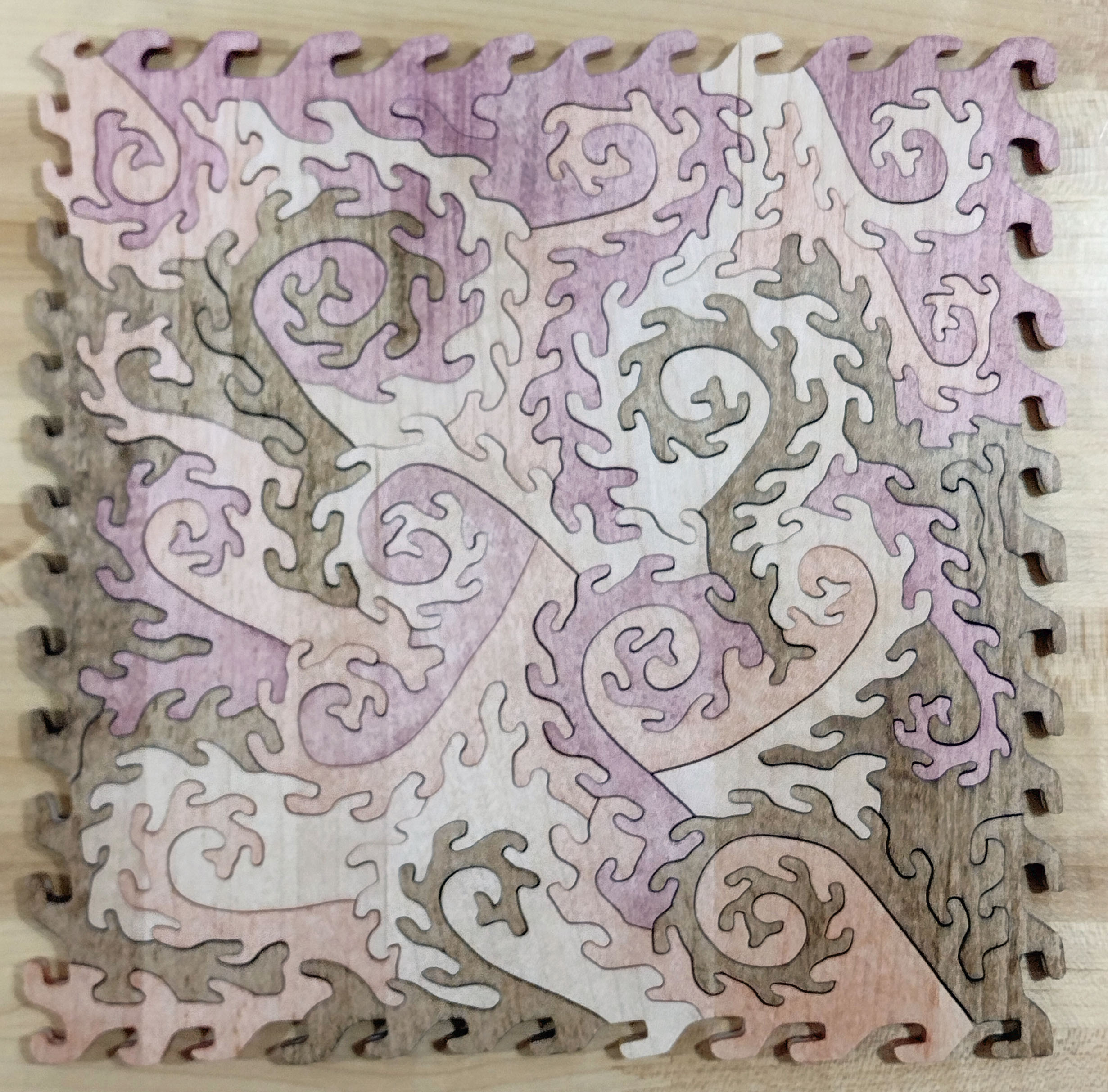
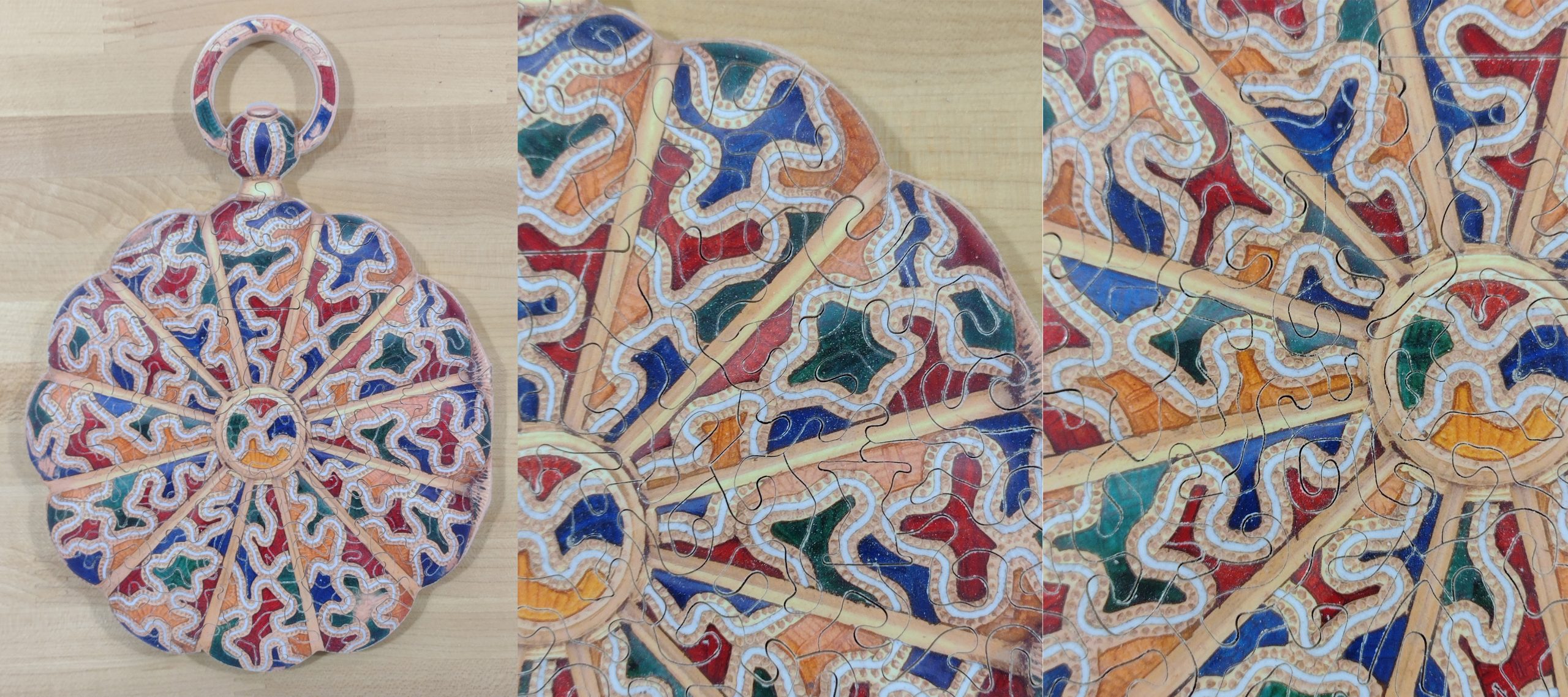
So, the 13 puzzles I provided for the exchange have minimal tear out on the backside and feel relatively smooth. About five of them are exceptional in that regard. All of them are good puzzles from a puzzling standpoint, but a few of them are not as smooth as I would have liked. The next two images show the front and back of one of the 13 puzzles exchanged.
Front of one of the puzzles
Back of one of the puzzles
Summary
These puzzles were a great project for me. I learned quite a bit in the process. When everything was just right, a nearly perfect double-sided puzzle resulted.
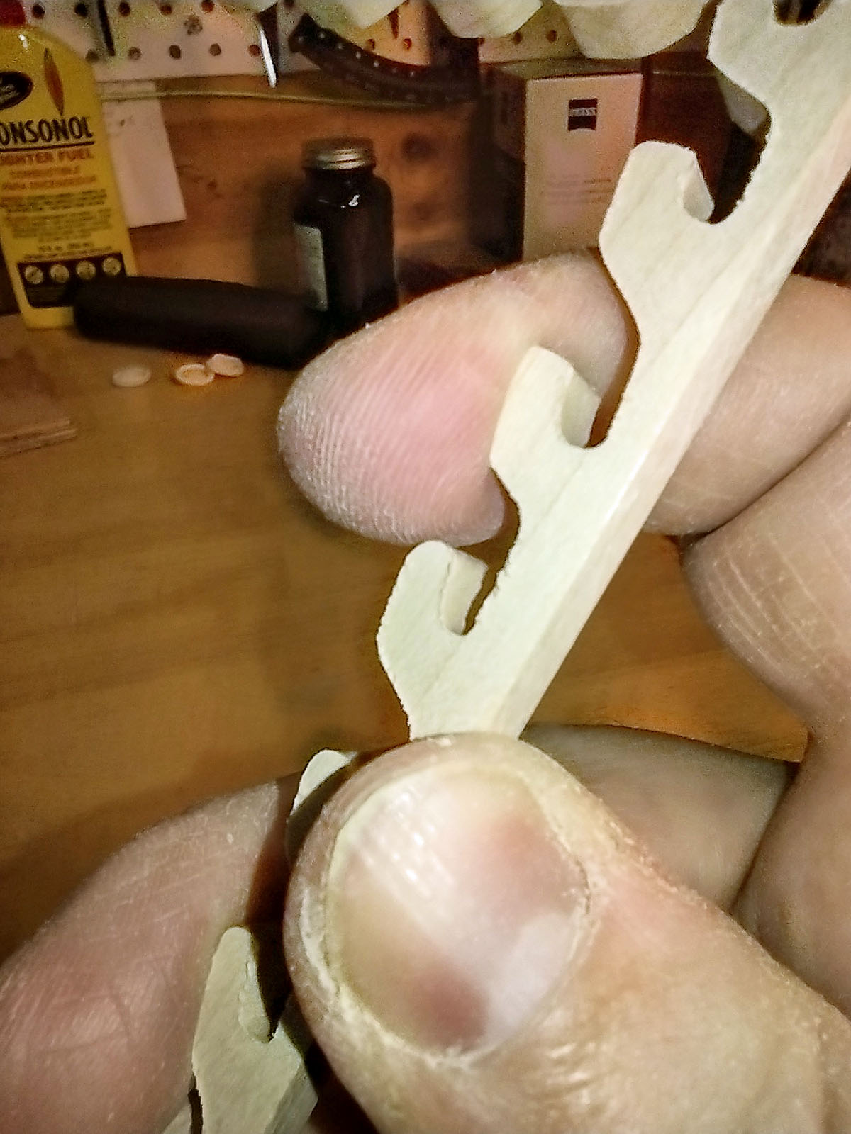
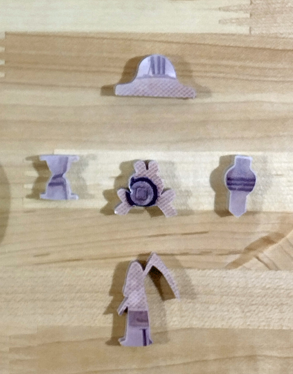
Each puzzle had five figurals. In the center was a reduced size frog signature piece. At the three o’clock position was a wristwatch. 12 o’clock was a mantel clock. 9 o’clock was an hourglass. 6 o’clock was meant to be Old Man Time but ended up being the grim reaper.
Figural pieces
I cut a total of 18 of these puzzles. The last 13 cut were used in the puzzle exchange for the 2024 Puzzle Parley. Of the first five cut, two were sold as “seconds” at the table sales during the Parley. Three remain with me as of this writing. I will not be listing them on my Etsy store, as I consider them to be seconds. If anyone is interested in obtaining one, contact me and we can work something out.
I also had 8 of the puzzles that resulted from the backing boards. Two of these were painted as examples of what could be done with them. Six were left bare as “Bare Naked Wood Puzzles”. All of them were taken to the Parley as well, and five were sold. The remaining ones are available for sale by contacting me direct.
Bare Naked Wood Puzzle, one painted kind of abstract, one painted with a scene
I did some other experiments while cutting these as well. Not part of the challenge per se, nor part of this write up, but I experimented with using 5 different types of wood, several types of different papers including two metallic papers, and different finishes to protect the paper.